Portable lampblack filter, lampblack filtering method and application
A fume filter, portable technology, applied in the filter field, can solve the problems of damage to the respiratory system, lung damage, lung injury, etc., and achieve the effect of easy installation, maintenance and portability, and good purification effect
- Summary
- Abstract
- Description
- Claims
- Application Information
AI Technical Summary
Problems solved by technology
Method used
Image

Examples
Embodiment 1
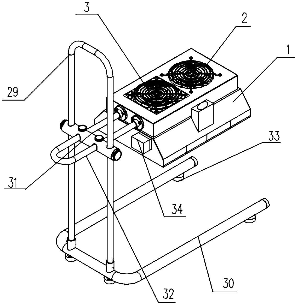
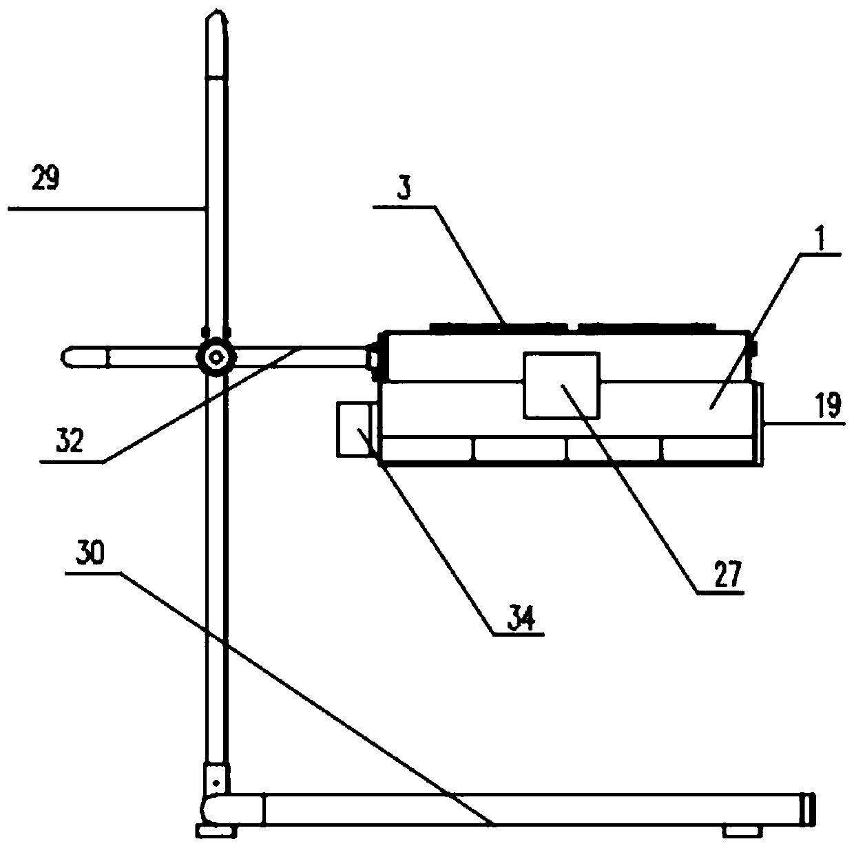
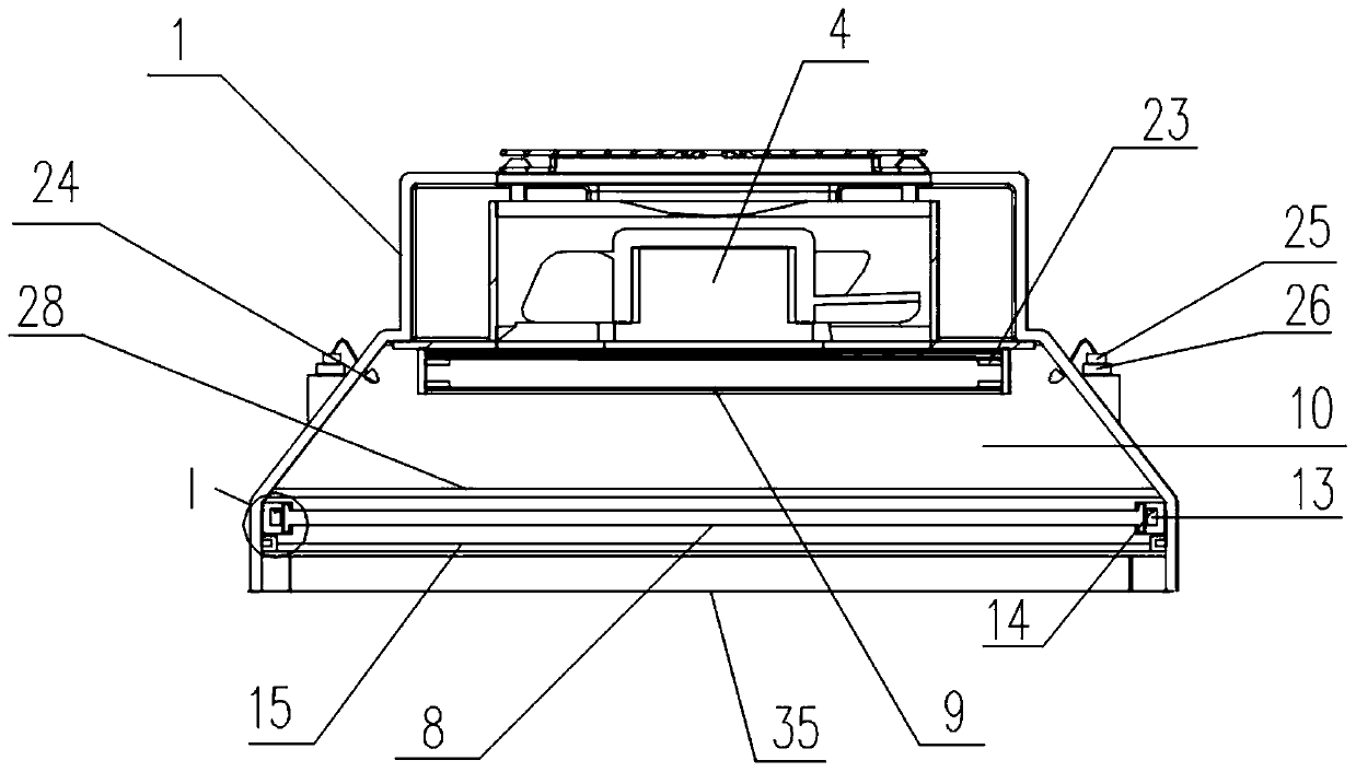
[0039] Such as Figure 1-7 As shown, the specific embodiment of the present invention provides a portable oil fume filter, including: a main body 1, a filter unit, a support unit and a charging power supply module. The main body has two air inlets (not shown in the figure) and two air outlets 2 . The air inlet is located on the bottom surface of the main body 1, and the air inlet is of a conventional structure and has no special structure, which will not be described in detail here. Air outlet 2 is positioned on main body 1 top surface, and air outlet 2 and air inlet are all provided with outer cover (air outlet outer cover 3 such as figure 1 As shown), the main body 1 is provided with an axial flow fan 4, the axial flow fan 4 is facing the air outlet 2, the axial flow fan 4 is installed on the fan mounting plate 5 of the main body 1, and the fan mounting plate 5 is located on the axial flow The outer periphery of the blower fan 4 is provided with a plurality of deflectors 6...
Embodiment 2
[0050] A specific embodiment of the present invention provides a method for filtering cooking fume produced by barbecue, which adopts the filter of Embodiment 1 and includes the following steps:
[0051] Prepare oil fume lotion and put it into the lotion storage bottle;
[0052] Turn on the fan to introduce the oily fume into the filter unit from the air inlet, and after one-time filtration of the first filter layer, the large particles in the oily fume are intercepted;
[0053] At the same time, turn on the micro pressure pump, and the remaining oil fume entering the air storage room will be wrapped in it under the action of atomized lotion, a small part of which will hang on the inner wall of the air storage room, and most of the droplets will be blown by the fan. Continue to enter the second filter layer for processing; the processed gas is discharged from the air outlet. The test results of oil fume concentration before and after treatment are shown in Table 1.
Embodiment 3
[0055] The specific embodiment of the present invention provides a method for filtering oily fume produced by barbecue. The operation method and environment for generating oily fume are about the same as in Example 2. The difference between the filter used and Example 1 is that no atomizing nozzle is designed in the air storage chamber , and there are no lotion storage bottles and other related devices, and the second filter layer has only one layer of acrylic resin layer structure. Processing method is the same as embodiment 2 except atomization process. The test results of oil fume concentration before and after treatment are shown in Table 1.
PUM
 Abstract
Description
Claims
Application Information