Multi-stirring-shaft vacuum microwave oven special for powder and heating method

A vacuum microwave oven and multi-stirring technology, which is applied to electric furnace heating, maintenance of heating chamber, lighting and heating equipment, etc., can solve the problem of single function of high temperature heating furnace, limited heating method of heat treatment environment or inconvenient change of heat treatment environment, and whether the heating is uniform or not. Affect product quality and other issues

Inactive Publication Date: 2020-08-11
株洲弗拉德科技有限公司
View PDF5 Cites 2 Cited by
  • Summary
  • Abstract
  • Description
  • Claims
  • Application Information

AI Technical Summary

Problems solved by technology

[0002] The environment in the high-temperature furnace required for the heat treatment of powder products is different. Some powders need to be prepared in a vacuum state, while some need to be carried out in an atmospheric pressure environment; the atmosphere conditions required for powder heat treatment also include oxidizing atmosphere, reducing atmosphere, etc.; and for For the selection of heating methods, some powders only need traditional resistance heating, while for powders with hi

Method used


Image

  • Multi-stirring-shaft vacuum microwave oven special for powder and heating method
  • Multi-stirring-shaft vacuum microwave oven special for powder and heating method

Examples


Embodiment 1

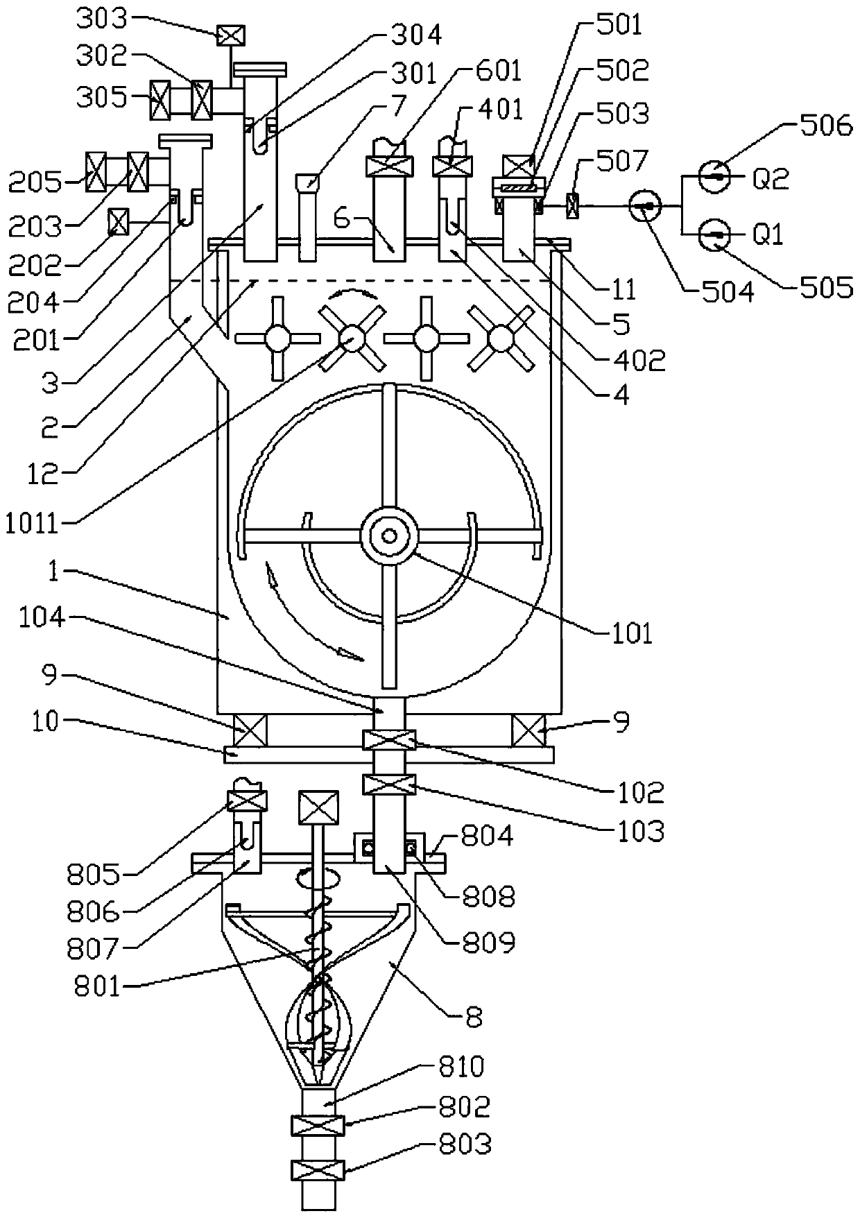
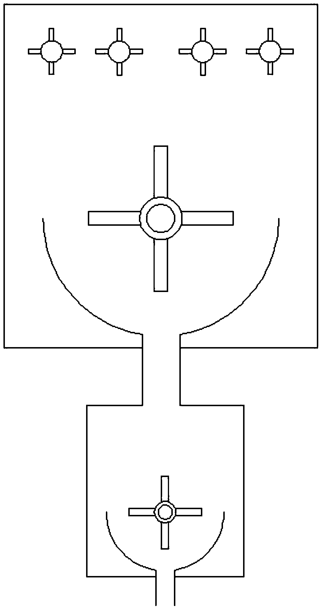
[0027] Such as figure 1 As shown, a vacuum microwave oven with multi-stirring shafts dedicated to powder includes a heating furnace body 1, a cooling furnace body 8, a load cell 9, and a lower vacuum channel 2 and an upper vacuum channel 2 arranged on the furnace cover 11 of the heating furnace body 1. Channel 3, exhaust channel 4, microwave input pipe 5, feed pipe 6, temperature measuring part 7, as shown in the figure, the heating furnace body 1 is a horizontal structure (that is, the stirring shaft is arranged horizontally), including the furnace body and Furnace cover 11, heating furnace body 1 The furnace body is a container welded by a U-shaped groove at the bottom and a rectangular flat plate, and a resistance heating element and an insulating layer are arranged in the shell on the outer side of the inner wall of the U-shaped groove that is in contact with the material. The outside is also provided with a forced cooling air duct (not shown in the figure); the bottom of ...

Embodiment 2

[0037] This embodiment still adopts the multifunctional horizontal vacuum microwave oven dedicated to the powder described in Embodiment 1. The difference is that the powder that undergoes heat treatment in this embodiment is a powder that needs to undergo redox reactions, such as putting iron oxide into the furnace at the same time Powder and carbon powder, the two can react under high-temperature atmospheric pressure environment, and the vacuum modules 205, 305 and their accessories do not need to work at this time. Similarly, the resistance heating element in the shell of the heating furnace body 1 can also be seen to be different. Disabled or traded off.


PUM


Abstract

The invention provides a multi-stirring-shaft vacuum microwave oven special for powder. The vacuum microwave oven comprises a heating oven body, a cooling oven body, a weighing sensor, lower vacuum channels, an upper vacuum channel, an exhaust channel, a microwave input pipe, a feeding pipe and a temperature measuring component; and high-speed stirring shafts and a low-speed stirring shaft are arranged in the heating oven body. According to the multi-stirring-shaft vacuum microwave oven special for the powder, the oven can work in a vacuum state and can also work in an atmospheric pressure state; the oven can work in a plasma environment microwave heating state and can also work in a non-plasma environment microwave heating state; the oven can work in a microwave heating state, can work ina resistance heating state and can also work in a microwave heating and resistance heating dual-heating state; the oven can work in an oxidizing atmosphere state, can work in a reducing atmosphere state and can also work in other atmosphere states; and based on the action of the multiple stirring shafts, the heat treatment on materials can be sufficiently performed.

Description

technical field [0001] The invention relates to the technical field of powder heat treatment, and more specifically, relates to a multi-shaft vacuum microwave oven dedicated to powder. Background technique [0002] The environment in the high-temperature furnace required for the heat treatment of powder products is different. Some powders need to be prepared in a vacuum state, while some need to be carried out in an atmospheric pressure environment; the atmosphere conditions required for powder heat treatment also include oxidizing atmosphere, reducing atmosphere, etc.; and for For the selection of heating methods, some powders only need traditional resistance heating, while for powders with higher quality requirements, microwave heating is required; the function of high-temperature heating furnaces in the prior art is relatively single, and a single heat treatment furnace can provide The heat treatment environment and heating methods are limited or it is not easy to change ...

Claims


Application Information

Patent Timeline
IPC IPC(8): F27D7/06F27D9/00F27D11/02F27D21/00
CPCF27D7/06F27D9/00F27D11/02F27D21/0014F27D21/0035F27D2007/066F27D2009/0013
Inventor 言伟雄
Owner 株洲弗拉德科技有限公司
Why Eureka
Try Eureka