Molar back push device

A technique of molar and premolar, applied in dentistry, orthodontics, prosthetics, etc., can solve the problems of tooth rotation, molar buccal tilt, etc., to avoid tooth rotation, improve connection strength, and increase the effect of connection area

Pending Publication Date: 2020-08-14
PEKING UNIV SCHOOL OF STOMATOLOGY
View PDF0 Cites 0 Cited by
  • Summary
  • Abstract
  • Description
  • Claims
  • Application Information

AI Technical Summary

Problems solved by technology

In traditional methods, such as extraoral arches and class II traction, the molar setback effect largely depends on the cooperation of the patient. In contrast, the use of i...

Method used


Image

  • Molar back push device
  • Molar back push device

Examples


Embodiment 1

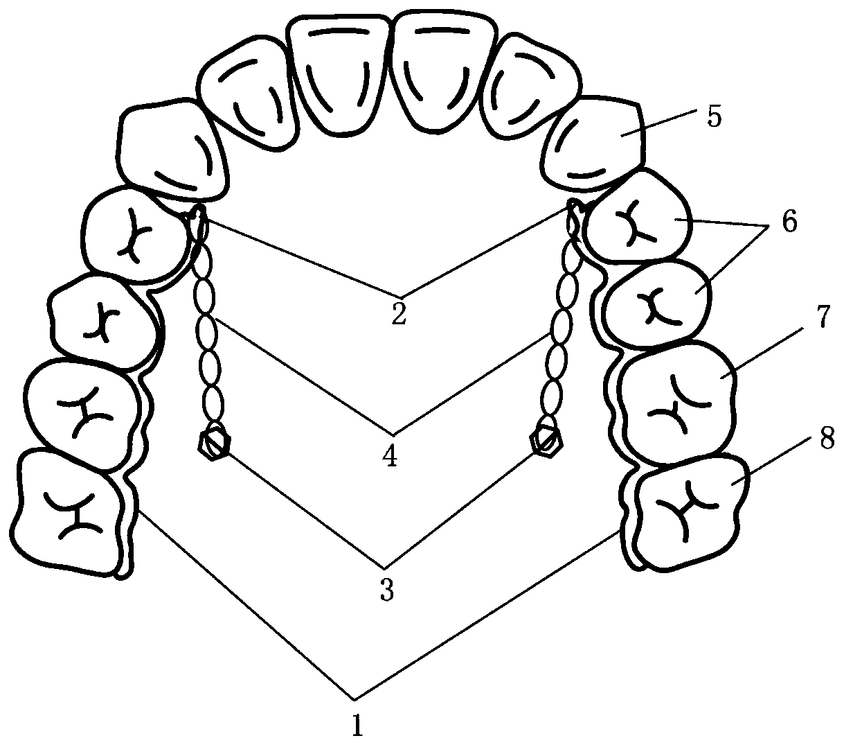
[0047] figure 1 A schematic structural view of the molar pushback device of this embodiment is shown.

[0048] Such as figure 1 As shown, the pushback molar device includes:

[0049] A pair of retaining parts are respectively arranged on both sides of the upper jaw of the oral cavity. Each retaining part includes a retaining part 1 and a traction hook 2. The retaining part 1 is in the form of a sheet with a thickness of 0.4 mm and bonded by a resin adhesive On the crown-palatal side of the premolars 6, first molars 7, and second molars 8 on the maxillary side of the oral cavity, the traction hook 2 is cylindrical, with a diameter of 1 mm, and is arranged at the proximal end of the retainer 1, and extends toward the proximal Extending in the middle direction, wherein, the retainer 1 of each retainer part and the traction hook 2 are integrally formed;

[0050] Two implant nails 3, each implant nail 3 is located between the palatal roots of the first molar 7 and the second mol...

Embodiment 2

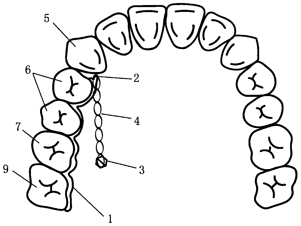
[0056] figure 2 A schematic structural view of the molar pushback device of this embodiment is shown.

[0057] Such as figure 2 As shown, the difference between this embodiment and Embodiment 1 is that: the retaining part, the implant nail 3 and the connecting part 4 are all one, and the retaining part 1 of the retaining part is bonded to the side of the upper jaw of the oral cavity through a resin adhesive. On the palatal side of the crowns of the premolars 6, the first molars 7 and the second molars 8, the connecting piece 4 is connected between the implant nail 3 and the traction hook 2 of the retaining part. For patients requiring only unilateral molar setback.

[0058] When designing, first use a computer to design a single-sided retention part that fits the patient's molar tooth surface according to the patient's dental arch data and does not affect the occlusion with the opposing jaw; then use 3D printing technology to print out the retention part in one piece . W...


PUM

PropertyMeasurementUnit
Thicknessaaaaaaaaaa
Diameteraaaaaaaaaa

Abstract

The invention discloses a molar back push device. The device comprises at least one retention part, at least one implantation nail and at least one connecting piece; each retention part comprises a retention part and a traction hook; the retention parts are connected to the dental crown palate sides of premolar, first molar and second molar on one side of the upper jaw of an oral cavity; the traction hooks are respectively arranged at the near-middle ends of the retention parts; the implantation nails are in one-to-one correspondence with the retention parts, and each implantation nail is located between the palatal root of the first molar and the palatal root of the second molar on the same side as one retention part and is close to the second molar; and each connecting piece is connectedbetween one planting nail and one traction hook on the same side. Through the device, the molars can be moved backwards as much as possible within a physiological limit, stress application is more flexible, and adverse molar buccal inclination and tooth rotation are avoided. Meanwhile, the bonding area is increased, bonding strength is improved, intraoral stability of the device is optimized, clinical use is facilitated, and the device has good comfort.

Description

technical field [0001] The invention belongs to the technical field of orthodontics, and more particularly relates to a device for pushing back molars. Background technique [0002] Pushing the molars to the distal is a commonly used orthodontic treatment method. It has a good treatment effect on Angle’s Class II patients with mild to moderate crowding, and can change the borderline cases between extraction and non-extraction into non-extraction range, making the correction process easier. In traditional methods, such as extraoral arches and class II traction, the molar setback effect largely depends on the cooperation of the patient. In contrast, the use of implant-assisted molar pushback has high patient comfort and absolute control over the molars. However, there are still problems such as molar buccal inclination and tooth rotation. [0003] Therefore, it is expected to develop a device for pushing back the molars, which can move the maxillary molars as a whole as far ...

Claims


Application Information

Patent Timeline
IPC IPC(8): A61C7/00A61C7/08
CPCA61C7/00A61C7/08
Inventor 韩冰宋广瀛卫彦陈贵吕汶諠余婷婷张云帆彭丽颖
Owner PEKING UNIV SCHOOL OF STOMATOLOGY
Why Eureka
Try Eureka