Supercharge Your Innovation With Domain-Expert AI Agents!

Corrugated carton printing machine with stacking and paving function

A corrugated box and printing machine technology, applied to printing machines, rotary printing machines, printing, etc., can solve problems such as low efficiency, high manual labor intensity, and inability to meet production needs, and achieve the effect of increasing friction and flexible control

Active Publication Date: 2020-08-14
南通宇成印务有限公司
View PDF5 Cites 0 Cited by
  • Summary
  • Abstract
  • Description
  • Claims
  • Application Information

AI Technical Summary

Problems solved by technology

[0003] Corrugated box printing machines on the market usually need to manually place the cartons on the printing table, and the stacked corrugated boxes need to be spread and staggered before printing can be carried out. After printing, the laid corrugated boxes also need to be manually stacked Together, this method is inefficient and labor-intensive, which can no longer meet the current production needs. In addition, the traditional printing machine does not move through two conveyor belts with speed differences when paving. The corrugated cartons together are gradually dislocated, and it is impossible to control the size of the dislocation area, that is, the printing area, by controlling the speed difference between the two conveyor belts. It is not flexible to use. Finally, there is no push mechanism at the bottom of the two conveyor belts, and it is impossible to pass through the top column on the push mechanism. To flexibly control the friction between the upper surface of the conveyor belt and the lower surface of the corrugated box, the paving effect is poor

Method used


Image

  • Corrugated carton printing machine with stacking and paving function
  • Corrugated carton printing machine with stacking and paving function
  • Corrugated carton printing machine with stacking and paving function

Examples


Embodiment Construction

[0031] It should be noted that the embodiments in this application and the features in the embodiments can be combined with each other if there is no conflict.

[0032] In the description of this application, it should be noted that the terms "installation", "connection", and "connection" should be interpreted broadly unless otherwise clearly specified and limited. For example, it can be a fixed connection or a detachable connection. Connected or integrally connected; it can be a mechanical connection or an electrical connection; it can be directly connected or indirectly connected through an intermediate medium, and it can be the internal communication between two components. For those of ordinary skill in the art, the specific meanings of the above terms in this application can be understood through specific circumstances.

[0033] In order to facilitate the understanding of the present invention, the present invention will be described more fully below with reference to the rele...


PUM


Abstract

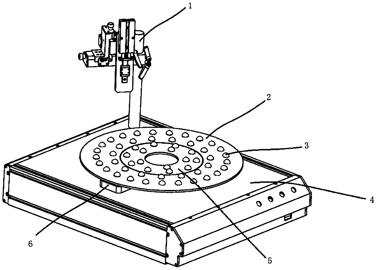
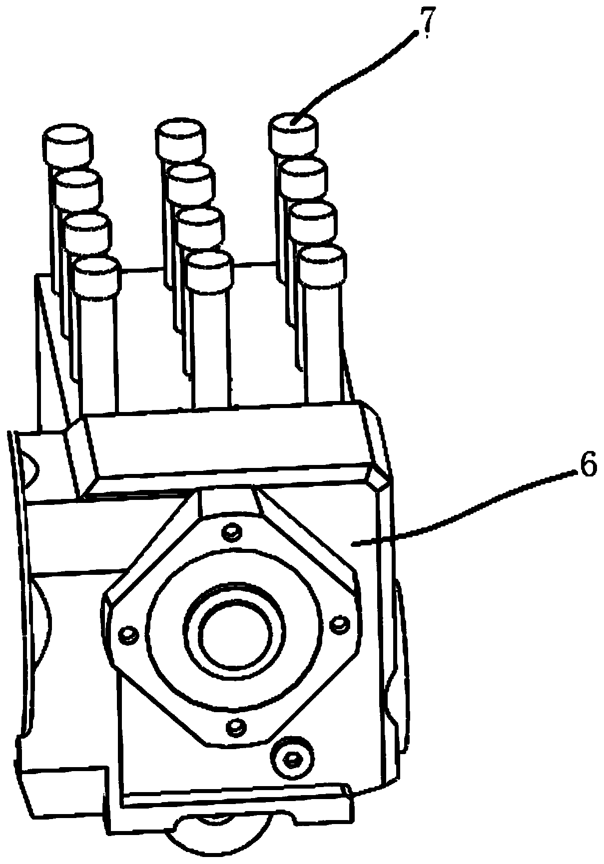
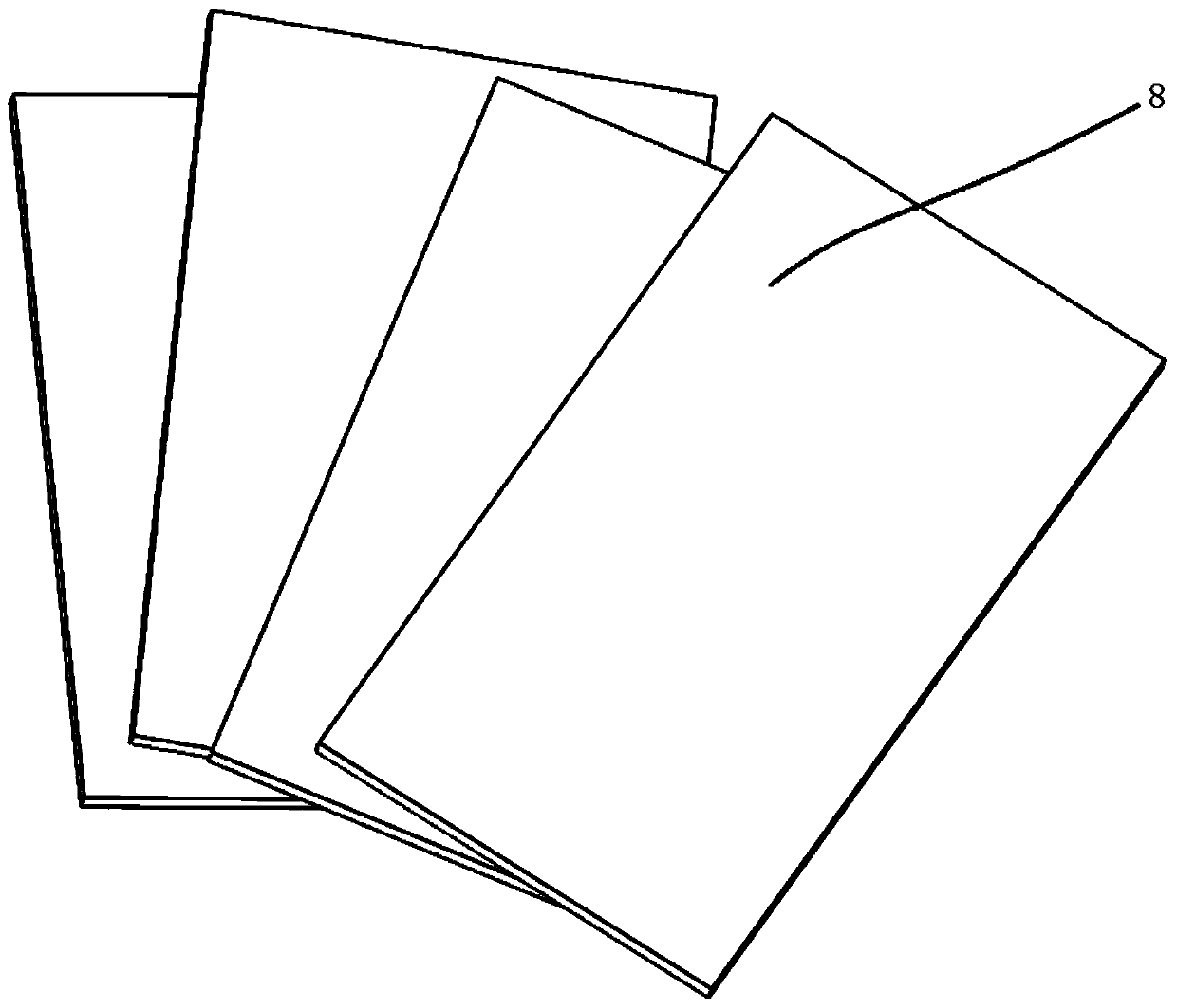
The invention discloses a corrugated carton printing machine with a stacking and paving function. The corrugated carton printing machine comprises a material falling assembly and a conveying assemblylocated below the material falling assembly; the conveying assembly comprises a first conveying belt and a second conveying belt which are concentrically arranged in a sleeving mode, and the first conveying belt is located on the outer side of the second conveying belt; the material falling assembly comprises a material falling channel and a baffle arranged at the end of the material falling channel, and the baffle can adjust the discharging speed; the moving speed of the first conveying belt is a first speed, the moving speed of the second conveying belt is a second speed, and the first speedis not smaller than the second speed; a plurality of anti-skid convex points are arranged on the surface of each of the first conveying belt and the second conveying belt; in the moving process of the conveying assembly, stacking and paving of corrugated cartons are conducted through the speed difference between the first conveying belt and the second conveying belt; and a printing mechanism is arranged above one side of the conveying assembly, and the paved corrugated cases are printed through a printing mechanism.

Description

Technical field [0001] The invention relates to the field of printing or stacking paving, in particular to a corrugated box printing machine with stacking paving function. Background technique [0002] At present, because of its light weight, low cost, easy processing, and convenient storage and transportation, corrugated boxes have become important transportation packaging containers and are widely used in food, beverages, household appliances, medicine, daily necessities, and electromechanical products. When using corrugated boxes for packaging, it is usually necessary to print text, patterns, etc. on its outer surface to indicate the type and name of the internally packaged items. In the printing of corrugated boxes, corrugated box printers are usually used, which can The required text, patterns and other information are printed on the surface of the carton box, generally including the process flow of plate loading, ink coating, embossing, and paper feeding. [0003] The corrug...

Claims


Application Information

Patent Timeline
Patent Type & Authority Applications(China)
IPC IPC(8): B41F17/00B65H5/02B65H29/18B65H31/02
CPCB41F17/04B65H5/021B65H29/18B65H31/02B65H2701/1131
Inventor 冯杏妥匡宝志
Owner 南通宇成印务有限公司
Features
  • R&D
  • Intellectual Property
  • Life Sciences
  • Materials
  • Tech Scout
  • Unparalleled Data Quality
  • Higher Quality Content
  • 60% Fewer Hallucinations
Learn More