
Assembly line conveying structure for piston rod of hydraulic oil cylinder

A technology of hydraulic cylinder and piston rod, applied in the field of hydraulic cylinder piston rod pipeline conveying structure, can solve the problems of unfixed position, high replacement cost, hard material of transmission belt, etc., and achieve convenient disassembly and assembly of conveyor belt, prolong service life, and simple maintenance. Effect

Inactive Publication Date: 2020-08-14
湖北统联汽车零部件有限公司
View PDF1 Cites 1 Cited by
  • Summary
  • Abstract
  • Description
  • Claims
  • Application Information

AI Technical Summary

Problems solved by technology

[0007] In order to solve the above-mentioned technical problems, the present invention provides a hydraulic cylinder piston rod assembly line conveying structure, to solve the belt transmission work in the prior art, because the transmission belt lacks a limiting structure for the piston rod, the whole is relatively flat, and the cylinder piston rod It will slide left and right on the conveyor belt, the position is not fixed, and automatic grabbing cannot be realized. The rod body will collide with the side baffle of the conveyor device, which will affect the surface quality of the rod body; the material of the transmission belt is relatively hard, which is easy to scratch the rod body and affect the smoothness of the piston rod. , after the transmission belt is damaged, it needs to be replaced as a whole, which will be more troublesome in disassembly and maintenance, and the problem of high replacement cost

Method used


Image

  • Assembly line conveying structure for piston rod of hydraulic oil cylinder
  • Assembly line conveying structure for piston rod of hydraulic oil cylinder
  • Assembly line conveying structure for piston rod of hydraulic oil cylinder

Examples


Embodiment

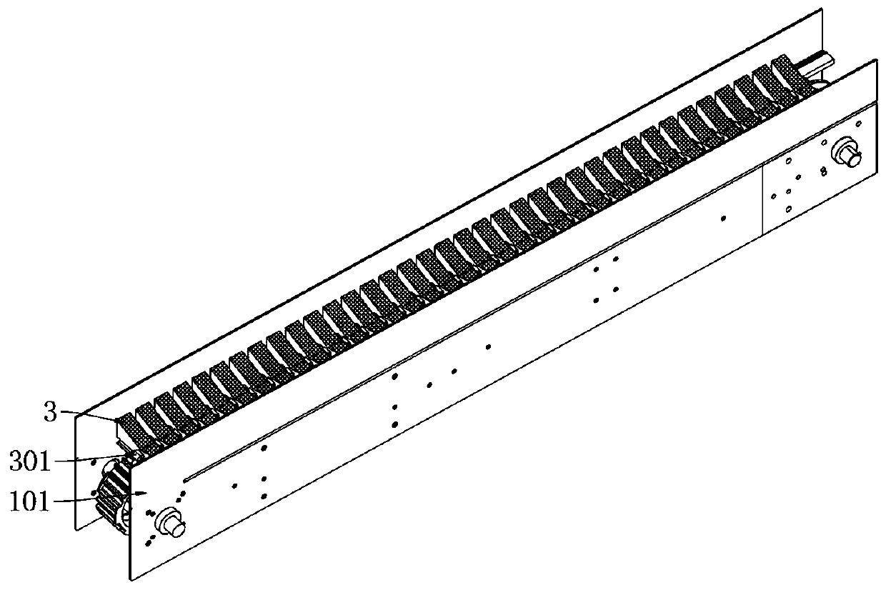
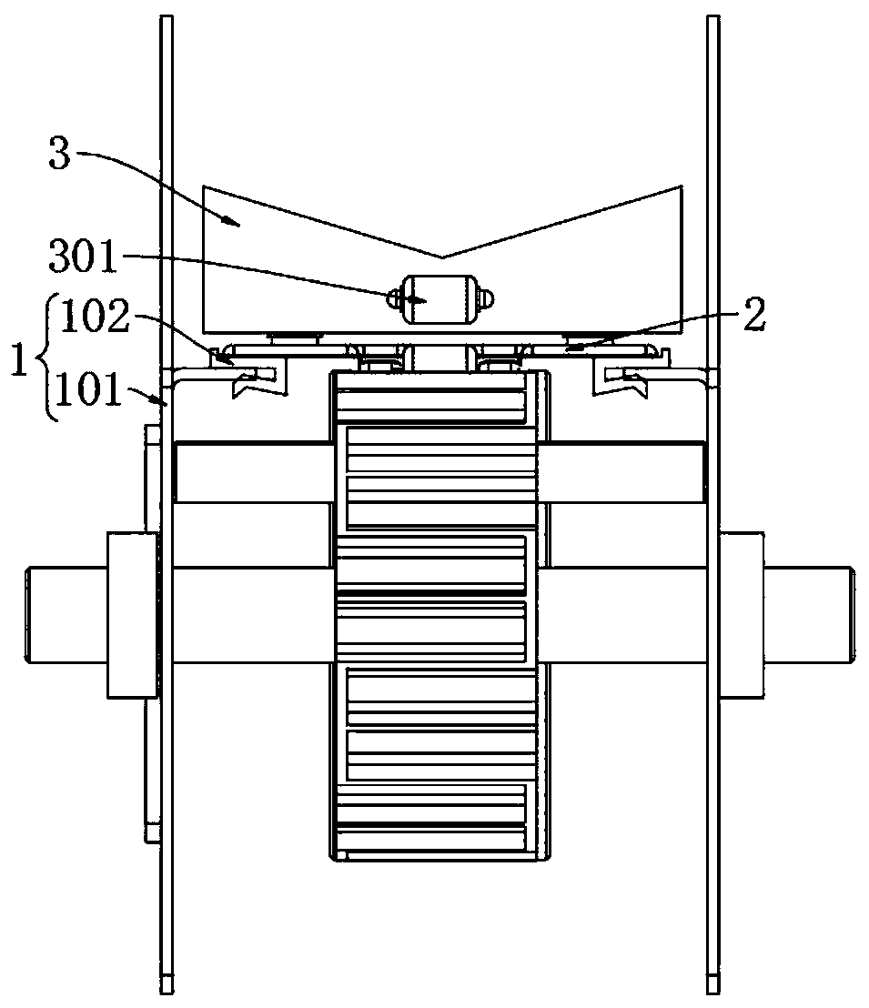
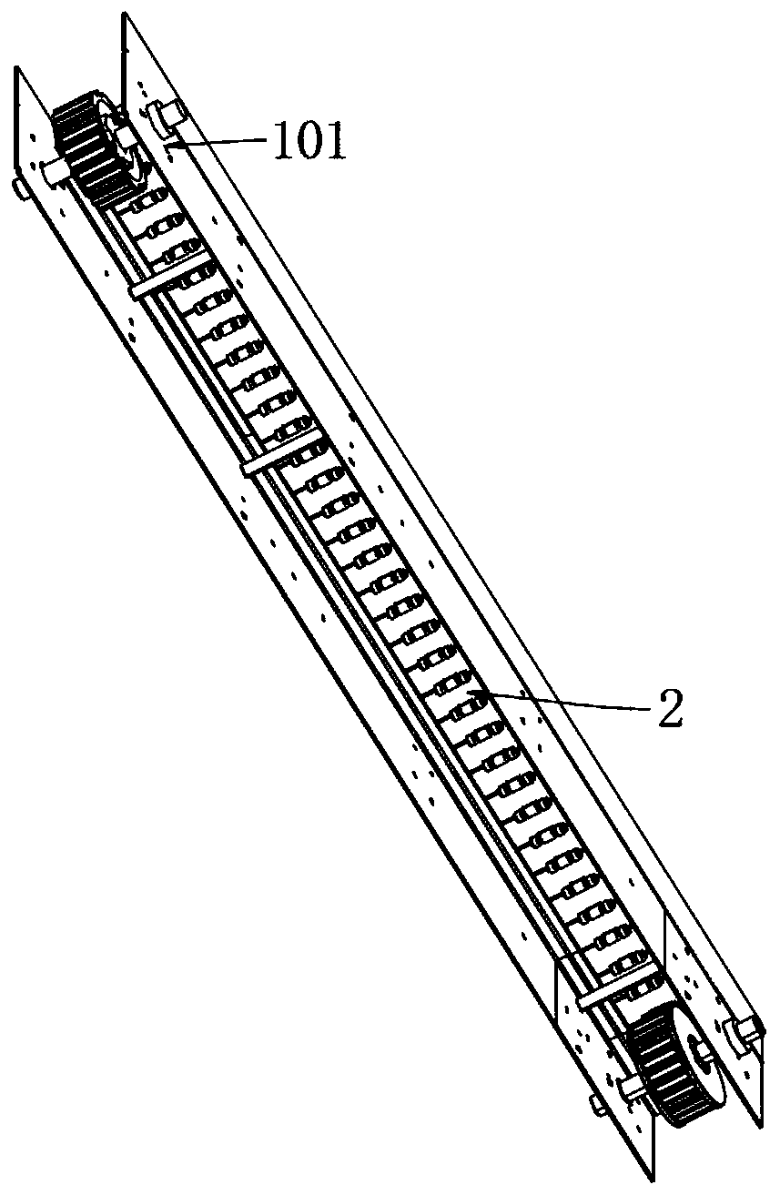
[0032] as attached figure 1 to attach Figure 7 Shown:

[0033] The present invention provides a hydraulic cylinder piston rod assembly line conveying structure, including a supporting mechanism 1;

[0034] The support mechanism 1 is symmetrically installed with two rotationally connected sprockets, and two rectangular support plates are installed on the support mechanism 1; The chain plates 2 are connected to each other through pin shaft hinges; the chain plates 2 form a transmission belt after being connected, and the transmission belt is connected with the sprocket through the hinge, and each chain plate 2 is clamped with a V-shaped fixed block 3; several V The fixed block 3 is also connected to each other through a pin hinge for transmission, and an elastic shaft 4 is placed on the V-shaped fixed block 3, and the V-shaped fixed block 3 is a nylon material lower than the hardness of the rod body.

[0035] Wherein, the support mechanism 1 includes a baffle 101 and a limit...


PUM


Abstract

The invention provides an assembly line conveying structure for a piston rod of a hydraulic oil cylinder. The assembly line conveying structure comprises a supporting mechanism. The supporting mechanism is symmetrically provided with two rotatably connected chain wheels, and two rectangular supporting plates are mounted on the supporting mechanism; the chain wheels on the supporting mechanism willbe in clamping transmission to chain plates during rotation and the chain plates are interconnected by hinge pin hinges; the chain plates which are connected form a transmission belt, and the transmission belt is connected to the chain wheels through the hinges. A clamping block in threaded connection is arranged on the chain plate, a slot aligned with the clamping block is formed in a V-shaped fixed block, and the V-shaped fixed block is clamped on the chain plate through a groove directly, so that the V-shaped fixed block can be detached and replaced independently. Compared with detachmentof a conveyor belt, it is convenient, simple to repair and maintain and low in maintenance cost. According to clamping serial connection of the V-shaped fixed block, tension during transmission is increased by means of the hinges, and the service life of the V-shaped fixed block is prolonged.

Description

technical field [0001] The invention belongs to the technical field of piston rods of hydraulic oil cylinders, and more specifically relates to an assembly line conveying structure of piston rods of hydraulic oil cylinders. Background technique [0002] The piston rod is a connecting part that supports the work of the piston. Most of them are used in the cylinder and cylinder motion actuators. It is a moving part with frequent movements and high technical requirements. Taking the hydraulic cylinder as an example, it consists of cylinder barrel, piston rod (cylinder rod), piston and end cover. The quality of its processing directly affects the life and reliability of the entire product. With the rapid innovation of technology and the sharp rise of labor costs, automated production has become the most effective means of cost reduction that all walks of life have to give priority to. The piston rod of the hydraulic pressure cylinder needs to be continuously conveyed during the...

Claims


Application Information

Patent Timeline
IPC IPC(8): B65G17/12B65G17/36B65G17/42
CPCB65G17/123B65G17/36B65G17/42
Inventor 马强赵雄
Owner 湖北统联汽车零部件有限公司
Learn More