
Sewage treatment system

A technology of sewage treatment system and sewage pool, which is applied in water/sewage treatment, water/sewage treatment equipment, water/sewage multi-stage treatment, etc. Operation and other problems, to avoid hindering the operation of equipment, reduce equipment costs and space, and facilitate collection.

Inactive Publication Date: 2020-08-14
安徽清蓝环保工程有限公司
View PDF0 Cites 0 Cited by
  • Summary
  • Abstract
  • Description
  • Claims
  • Application Information

AI Technical Summary

Problems solved by technology

[0002] In the sewage treatment process, the grid is generally used for solid-liquid separation. However, the types of solid waste in the sewage are cumbersome, such as general solid waste with a certain volume and small-volume floc waste suspended in water. Two types of grids with different thicknesses must be used for the separation of solid waste. This is because the mesh of the coarse grid is too large to intercept fine flocs, while the surface of the fine grid is smooth and difficult to attach large volumes of solid waste. In the existing technology, in order to fully separate the solid waste from the sewage, two sets of grille equipment must be used, which takes up a lot of space and high equipment cost; in addition, the grabbing hooks on the grille in the prior art are generally fixed structures, and it is not suitable for garbage to be attached. Falling off, it is easy to accumulate on the grille, and even block the grille and hinder the operation of the grille

Method used


Image

  • Sewage treatment system
  • Sewage treatment system
  • Sewage treatment system

Examples


Embodiment 1

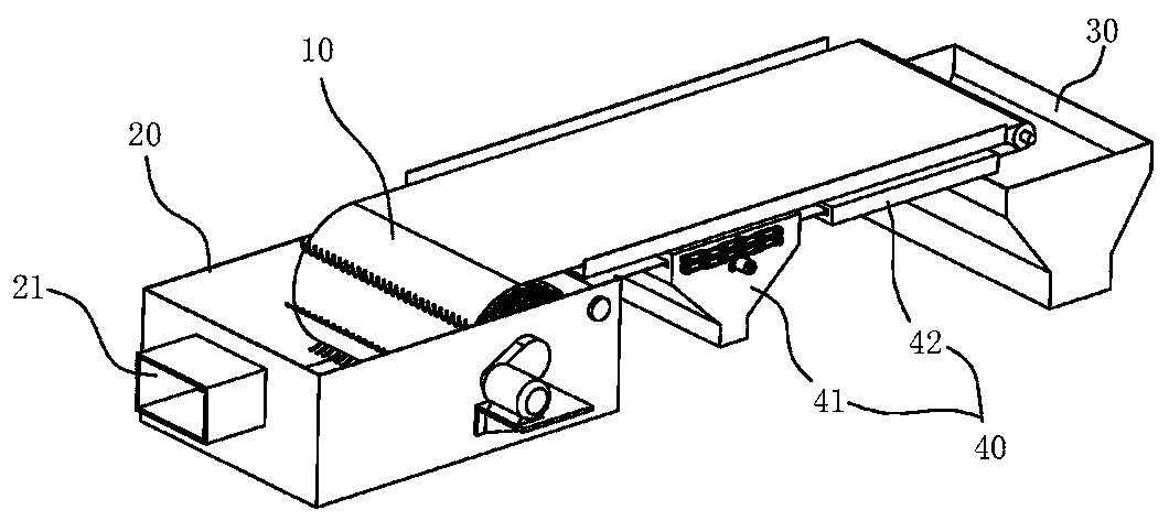
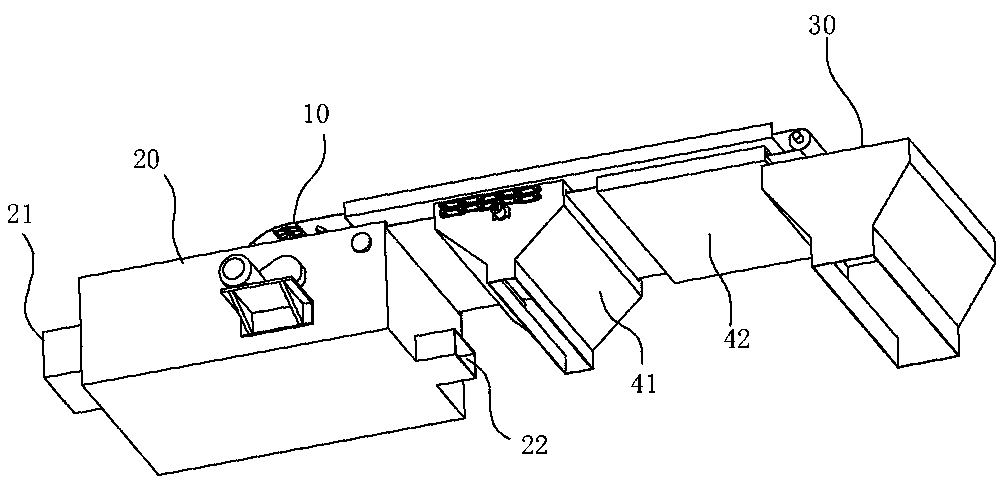
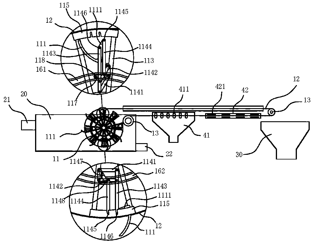
[0029] Such as Figure 11 Shown, a kind of sewage treatment system comprises solid-liquid separation device 1, anaerobic pond 2, anoxic pond 3, aerobic pond 4, sedimentation pond 5, disinfection pond 6 and outlet well 7; figure 1 , 2 , 3, the solid-liquid separation device 1 includes a sewage tank 20, a material transfer mechanism 10, a solid waste recovery mechanism 30 and a floc recovery mechanism 40; the sewage tank 20 is provided with a water inlet 21 and a water outlet 22 ;Such as Figure 4 As shown, the material transfer mechanism 10 includes a material transfer roller 11, a conveying mesh belt 12 and a guide roller 13; Immediately between the shifting roller 11 and the guide roller 13, the shifting roller 11 is provided with a movable hook 111, and the movable hook 111 is telescopically arranged on the roller surface of the shifting roller 11, and the movable hook 111 It is assembled to move between the following two stations: station one, the movable hook 111 protru...

Embodiment 2

[0037] A method for solid-liquid separation of sewage, comprising the steps of:

[0038] Step 1: discharge the mixed sewage with solid waste and floc into the sewage tank 20;

[0039] Step 2: filter the mixed sewage by using the material transfer mechanism 10, the material transfer mechanism 10 separates the solid waste and floc from the mixed sewage, and the filtered sewage enters the downstream reaction pool;

[0040] Step 3: the material transfer mechanism 10 transports the solid waste to the solid waste recovery mechanism 30, and the flocs are adsorbed on the conveying mesh belt 12 of the material transfer mechanism 10 and continue to be transported;

[0041] Step 4: The flocs enter the floc recovery mechanism 40 along with the conveyor belt 12, and the floc recovery mechanism 40 cleans the conveyor belt 12 and recovers the flocs adsorbed thereon.


PUM


Abstract

The invention belongs to the technical field of sewage treatment, and particularly relates to a sewage treatment system which comprises a solid-liquid separation device, an anaerobic tank, an anoxic tank, an aerobic tank, a sedimentation tank, a disinfection tank and a water outlet well, the solid-liquid separation device comprises a sewage pool, a material stirring and conveying mechanism, a solid garbage recycling mechanism and a floccule recycling mechanism; the sewage treatment system provided by the invention can be used for continuously and efficiently intercepting solid wastes with various volumes at one time in the early stage; multiple sets of grids are not needed, the equipment cost and occupied space are reduced, in addition, large-size garbage can be separated from an intercepting device more easily, subsequent solid garbage collection is facilitated, and the situation that garbage accumulation hinders equipment operation is avoided.

Description

technical field [0001] The invention belongs to the technical field of sewage treatment, and in particular relates to a sewage treatment system. Background technique [0002] In the sewage treatment process, the grid is generally used for solid-liquid separation. However, the types of solid waste in the sewage are cumbersome, such as general solid waste with a certain volume and small-volume floc waste suspended in water. Two types of grids with different thicknesses must be used for the separation of solid waste. This is because the mesh of the coarse grid is too large to intercept fine flocs, while the surface of the fine grid is smooth and difficult to attach large volumes of solid waste. In the existing technology, in order to fully separate the solid waste from the sewage, two sets of grille equipment must be used, which takes up a lot of space and high equipment cost; in addition, the grabbing hooks on the grille in the prior art are generally fixed structures, and it ...

Claims


Application Information

Patent Timeline
Patent Type & Authority Applications(China)
IPC IPC(8): C02F9/14
CPCC02F1/001C02F3/30C02F9/00C02F2001/007C02F2201/002C02F2303/04C02F2303/14
Inventor 钟灵胡遵琪赵晓东
Owner 安徽清蓝环保工程有限公司
Learn More