Device for cleaning carbon deposits on intake manifold

An intake manifold and carbon deposition technology, which is applied in the field of engine cleaning equipment, can solve the problems of time-consuming cleaning work, poor engine air intake, engine powerlessness, etc., and achieve the effect of convenient cleaning work.

Active Publication Date: 2020-08-18
ZHEJIANG BOYI TECH CO LTD
View PDF8 Cites 2 Cited by
  • Summary
  • Abstract
  • Description
  • Claims
  • Application Information

AI Technical Summary

Problems solved by technology

After the intake manifold has been used for a long time, the inner wall of the intake manifold is prone to carbon deposits. Severe carbon deposits will lead to poor air intake of the engine, resulting in engine weakness, idling vibration, and at the same time, the mixture is too rich, the power is obviously reduced, and the fuel consumption is also increased to a certain extent.
Therefore, after the engine works for a long time, it needs to be cleaned, especially to remove the carbon piles on the inner wall of the intake manifold. The existing method of removing carbon piles on the inner wall of the intake manifold is relatively primitive, mainly relying on manual cleaning, manual cleaning with brushes, etc. Carbon piles are removed by brushing, which is time-consuming and laborious to clean up

Method used


Image

  • Device for cleaning carbon deposits on intake manifold
  • Device for cleaning carbon deposits on intake manifold
  • Device for cleaning carbon deposits on intake manifold

Examples


Embodiment Construction

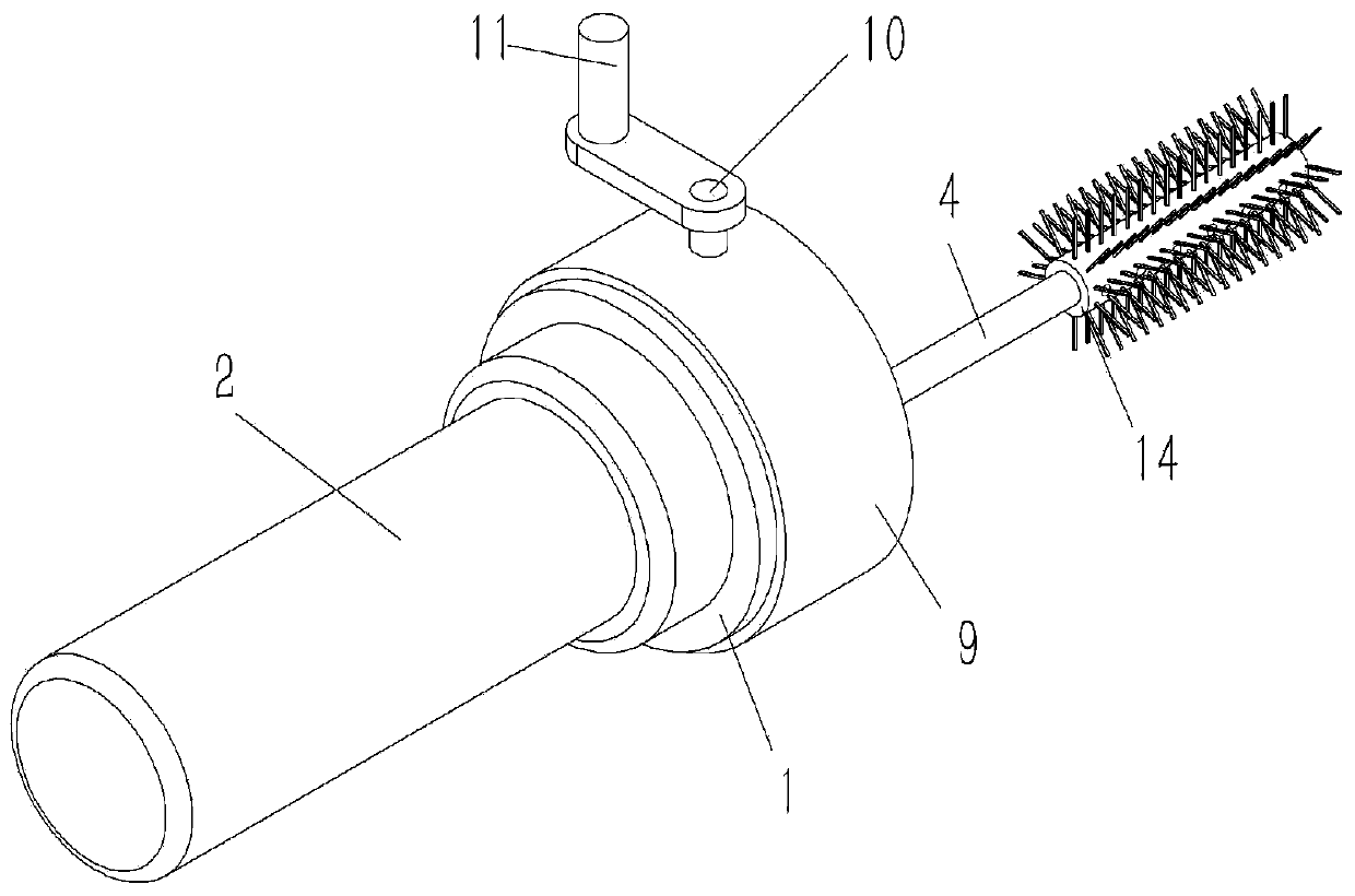
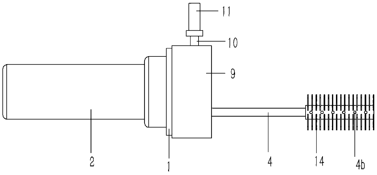
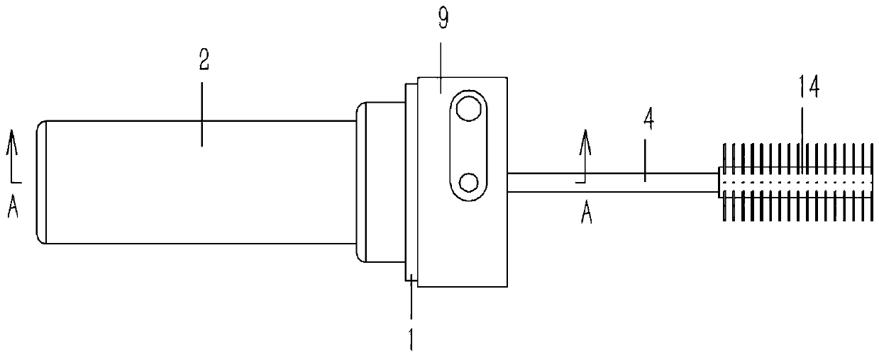
[0019] Example: see Figure 1 to 4 As shown, a device for cleaning carbon deposits in an intake manifold includes a cylindrical base 1, a circular recess 1a is formed on the right end of the base 1, and a handle 2 is fixed on the left end of the base 1. 2 A cleaning agent storage cavity 2a is formed in the cleaning agent storage cavity 2a of the handle 2, a screw 3 is inserted into the cleaning agent storage cavity 2a of the handle 2, and the right end of the screw 3 is inserted into the recess 1a of the base 1 through the base 1 and inserted into the sleeve The driven gear 6 is fixed, the outer ring of the recess 1a is inserted with an eccentric shaft 4, the eccentric shaft 4 is inserted on the base 1 and formed with a central hole 4a, the central hole 4a of the eccentric shaft 4 and the cleaning agent of the handle 2 The storage cavity 2a is in communication; the eccentric shaft 4 is fixed with a driving gear 5 and a driven bevel gear 7 in a sleeve, the driving gear 5 and the...


PUM


Abstract

The invention discloses a device for cleaning carbon deposits on an intake manifold. The device comprises a cylindrical base; a hand grip is fixed to the left end of the base, a cleaning agent storagecavity is formed in the hand grip, a lead screw is inserted into the cleaning agent storage cavity of the hand grip, the right end of the lead screw penetrates through the base and is inserted into aconcave table of the base, and a driven gear is inserted and fixed to the right end of the lead screw; an eccentric shaft is inserted into the outer ring of the concave table, the eccentric shaft isinserted into the base, a center hole is formed in the eccentric shaft, a driving gear and a driven bevel gear are fixed to the eccentric shaft in an inserted and sleeved mode, the driving gear is meshed with the driven gear, and a driven bevel gear is meshed with a driving bevel gear; an end cover is fixed to the right end of the base in an inserted and sleeved mode, a stop block is formed on thebottom face of the inner side of the end cover and abuts against the right end face of the driven gear, a transmission shaft is inserted into the stop block, one end of the transmission shaft is fixed into the driving bevel gear in an inserted mode, and the other end of the transmission shaft penetrates through the base and the end cover to be fixedly provided with a handle.

Description

Technical field [0001] The invention relates to the technical field of engine cleaning equipment, and more specifically to a device for cleaning carbon deposits in an intake manifold. Background technique [0002] As an important component of the engine's intake system, the intake manifold not only determines the initial intake air flow coefficient and the uniformity of each cylinder, but also determines the mixing efficiency of natural gas and air and the effective volume ratio. Therefore, it has an important influence on the engine's charging coefficient and the difference in the performance of each cylinder, and it affects the engine's power and torque output, air-fuel ratio coefficient and gas consumption rate. After long-term use of the intake manifold, the inner wall of the intake manifold is prone to carbon deposits. Serious carbon deposits will cause poor engine intake, causing engine weakness and idling jitter. At the same time, the mixture is too thick, power is signifi...

Claims


Application Information

Patent Timeline
Patent Type & Authority Applications(China)
IPC IPC(8): B08B9/043B08B9/045B08B13/00F02B77/04
CPCB08B9/0433B08B9/0436B08B9/045B08B13/00F02B77/04
Inventor 钟建斌
Owner ZHEJIANG BOYI TECH CO LTD
Why Eureka
Try Eureka