An intelligent turning device for shield segment steel skeleton

A steel frame and flipping device technology, applied in auxiliary devices, metal processing equipment, auxiliary welding equipment, etc., can solve the problems of increasing the number of steel frame processing steps, increasing work intensity, and the risk of processing accidents, so as to reduce processing accidents Possibility of risk, reduction of work intensity, and precise positioning

Active Publication Date: 2021-04-13
济南轨道中铁管片制造有限公司
View PDF10 Cites 0 Cited by
  • Summary
  • Abstract
  • Description
  • Claims
  • Application Information

AI Technical Summary

Problems solved by technology

[0003] Most of the current shield segment steel frame turning equipment has the following problems: (1) In the current conventional steel frame turning equipment, most of the simple sling devices are used to locate and fix the steel frame with the placement device, and then use Manual welding is time-consuming and labor-intensive, and it is impossible to weld the steel skeleton in multiple directions. First, it is easy to miss key welding points, and second, it is easy to cause the quality of welding points to be unable to be standardized and unified; (2) the current flip Most of the equipment welds the reinforcement cage and the steel mold separately. On the one hand, it will easily lead to a lower degree of stability of the final skeleton, and on the other hand, it will increase the number of steps in the processing of the reinforcement skeleton; When doing side points, it is often difficult to weld because the position of the steel skeleton does not correspond, which increases the work intensity, and because of the need to use manual methods, there is a possibility of processing accident risks

Method used


Image

  • An intelligent turning device for shield segment steel skeleton
  • An intelligent turning device for shield segment steel skeleton
  • An intelligent turning device for shield segment steel skeleton

Examples


Embodiment Construction

[0037] The following will clearly and completely describe the technical solutions in the embodiments of the present invention with reference to the accompanying drawings in the embodiments of the present invention. Obviously, the described embodiments are only some, not all, embodiments of the present invention. Based on the embodiments of the present invention, all other embodiments obtained by persons of ordinary skill in the art without making creative efforts belong to the protection scope of the present invention.

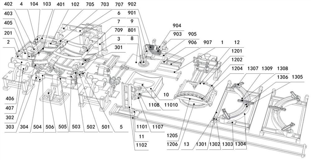
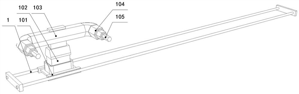
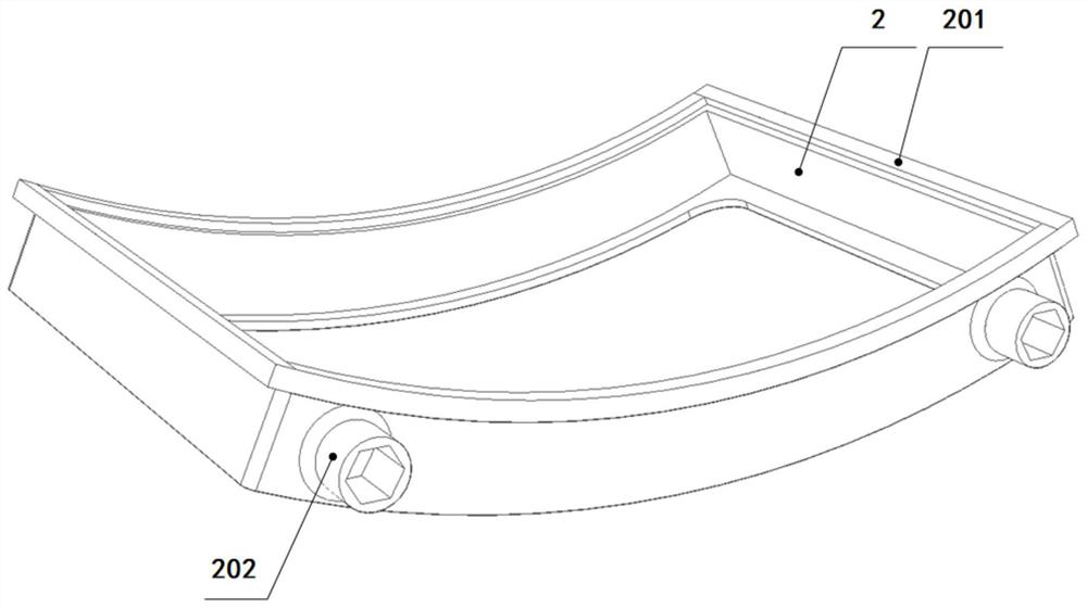
[0038] see Figure 1-11 , an intelligent flipping device for a shield segment steel skeleton, comprising a magnetic displacement system, a mold frame 12, a rolling system, a welding system, a locking system, a mold frame 26, a frame placing system, a placing table 10, and a displacement system , an inversion system, a side welding system; one side of the magnetic displacement system is provided with several rolling systems, the rolling system is used to place ...


PUM


Abstract

The invention discloses an intelligent overturning device for a steel bar skeleton of a shield segment, comprising a magnetic displacement system, a mold frame 1, a rolling system, a welding system, a locking system, a mold frame 2, a frame placing system, a placing table 1, and a displacement system , inversion system, and side welding system; the invention can realize the positioning and fixed point of the steel frame through the mutual cooperation of the magnetic displacement system and the rolling system, which is accurate and does not require manual intervention, saves time and effort in operation and can carry out all-round inspection of the steel frame Welding, greatly reducing the possibility of missing key welding points, while ensuring uniform quality of welding points. The mold frame combination can be locked through the locking system, and then the steel cage and the steel mold can be welded synchronously. Through the cooperation of the displacement system and the side welding system, it is possible to weld difficult, deep or weak points without welding. Affected by the position or orientation of the steel skeleton, the work intensity is reduced and the possibility of processing accidents is reduced.

Description

technical field [0001] The invention relates to the technical field of shield tunneling segment production and manufacturing, in particular to an intelligent flipping device for a steel bar skeleton of a shield tunneling segment. Background technique [0002] With the rapid development of the national economy, people's living standards are improving day by day, and the people's requirements for the quality of life are also constantly improving. A qualitative leap has taken place in all aspects of clothing, food, housing and transportation, among which the requirements for transportation are particularly prominent, as small as within the city or between communities. The upgrading of transportation and the reform of inter-city or inter-provincial transportation are the key areas of national infrastructure development. Most of the above-mentioned infrastructure industry upgrades need to involve tunnel operations, such as high-speed railway drilling tunnels, underground tunnels ...

Claims


Application Information

Patent Timeline
Patent Type & Authority Patents(China)
IPC IPC(8): B23K37/047
CPCB23K37/047
Inventor 李本友刘晓清吴海龙王久成李秀刚张华孟祥鹏张涛
Owner 济南轨道中铁管片制造有限公司
Why Eureka
Try Eureka