
Automatic automobile crankshaft grinding device

A crankshaft and automatic technology, which is applied in the direction of grinding automatic control device, grinding machine, grinding workpiece support, etc., can solve the problems of high labor intensity, low grinding quality, uneven grinding, etc. The effect of a high degree of automation

Inactive Publication Date: 2020-08-18
何效平
View PDF0 Cites 12 Cited by
  • Summary
  • Abstract
  • Description
  • Claims
  • Application Information

AI Technical Summary

Problems solved by technology

[0003] Grinding is one of the important processes in the processing of automobile crankshafts. The traditional grinding method is manual grinding by workers, which has the problems of low grinding quality and uneven grinding. Moreover, the labor intensity of workers is high and the grinding efficiency is not high.

Method used


Image

  • Automatic automobile crankshaft grinding device
  • Automatic automobile crankshaft grinding device

Examples


Embodiment 1

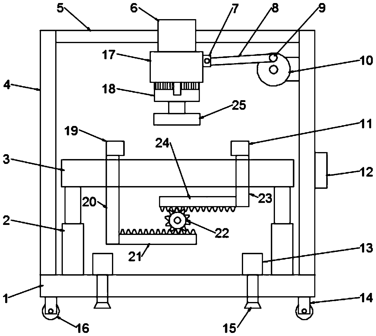
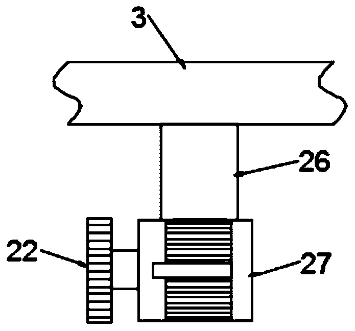
[0020] see Figure 1-2 , in the embodiment of the present invention, a kind of automobile crankshaft automatic polishing device comprises base plate 1, and the left and right sides of the upper end surface of base plate 1 are all connected with side support plate 4, and side support plate 4 is two left and right symmetrically arranged, and base plate 1 A workbench 3 is provided above; a hydraulic telescopic rod 2 is connected between the base plate 1 and the workbench 3, and the hydraulic telescopic rods 2 are two left and right symmetrically arranged, and a controller 12 is installed on the side of the side support plate 4, and the hydraulic pressure The telescopic rod 2 is electrically connected with the controller 12. The controller 12 can control the expansion and contraction of the hydraulic telescopic rod 2. The expansion and contraction of the hydraulic telescopic rod 2 drives the workbench 3 to lift. The top of the workbench 3 is provided with a grinding motor 18. The ...

Embodiment 2

[0028] see figure 1 , in the embodiment of the present invention, an automobile crankshaft automatic grinding device is different from embodiment 1 in that a second support 14 is installed on the bottom of the base plate 1, and a roller 16 is installed on the second support 14, and the roller 16 is 16 can move this automobile crankshaft automatic grinding device conveniently, also be equipped with hydraulic cylinder 13 on the base plate 1, the output end of hydraulic cylinder 13 is connected with support foot 15, and hydraulic cylinder 13 is electrically connected with controller 12, can control by controller 12 The hydraulic cylinder 13 drives the supporting foot 15 to move up and down. After the movement of the automatic crankshaft grinding device of the automobile is completed, the hydraulic cylinder 13 is used to drive the supporting foot 15 to descend, so that the roller 16 is separated from the ground, and the supporting foot 15 touches the ground and supports the automat...


PUM


Abstract

The invention relates to the technical field of crankshaft machining equipment, in particular to an automatic automobile crankshaft grinding device. The automatic automobile crankshaft grinding devicecomprises a bottom plate, side supporting plates are connected to the left side and the right side of the upper end face of the bottom plate, and a workbench is arranged above the bottom plate; a hydraulic telescopic rod is connected between the bottom plate and the workbench, a controller is installed on the side face of one of the side supporting plates, the hydraulic telescopic rod is electrically connected with the controller, a grinding motor is arranged above the workbench, an output shaft of the grinding motor is connected with a grinding disc, and the grinding motor is electrically connected with the controller; and the automatic automobile crankshaft grinding device further comprises a moving mechanism and a clamping mechanism. The moving mechanism can drive the grinding motor and the grinding disc to reciprocate left and right to automatically grind an automobile crankshaft, the automobile crankshaft can be clamped through the clamping mechanism, the situation that in the grinding process, the automobile crankshaft moves, and consequently the grinding process is affected is avoided, and the automation degree is high.

Description

technical field [0001] The invention relates to the technical field of crankshaft processing equipment, in particular to an automatic grinding device for an automobile crankshaft. Background technique [0002] The crankshaft of an automobile is the main rotating part of the engine. After the connecting rod is installed, it can undertake the up and down movement of the connecting rod and turn it into a circular motion. It is the most important part of the engine. It is made of carbon structural steel or ductile iron. The crank bearing is subjected to bending and torsional loads, so the crankshaft must have sufficient strength and rigidity. The journal surface must be wear-resistant, work evenly, and Well balanced. [0003] Grinding is one of the important processes in the processing of automobile crankshafts. The traditional grinding is a manual grinding method of workers, which has the problems of low grinding quality and uneven grinding, and the labor intensity of workers ...

Claims


Application Information

Patent Timeline
IPC IPC(8): B24B5/42B24B41/06B24B51/00
CPCB24B5/42B24B41/06B24B51/00
Inventor 何效平
Owner 何效平
Learn More