Rapid cooling and drying mechanism of vacuum aluminizing laminating machine and cooling method thereof

A rapid cooling and vacuum aluminum plating technology, applied in chemical instruments and methods, lamination devices, lamination auxiliary operations, etc., can solve the problems of inconvenient operation of cooling and drying mechanisms, inability to switch back and forth, etc.

Pending Publication Date: 2020-08-18
ANHUI SHUNTONG PACKAGING MATERIAL
View PDF8 Cites 3 Cited by
  • Summary
  • Abstract
  • Description
  • Claims
  • Application Information

AI Technical Summary

Problems solved by technology

[0004] The purpose of the present invention is to provide a rapid cooling and drying mechanism of a vacuum aluminum coating machine and its cooling method. The present invention sets three conveying belts on the top of the workbench and drives them through a conveying motor. Two adjacent conveying belts There are gaps between them. By setting heating rollers and cooling rollers under the conveying belt, the output rod of the second cylinder is controlled to extend and shrink, so as to control the sliding of the sliding rod in the arc-shaped chute, and cooperate with the first gear, The second gear is used to control the rotation direction of the gear central shaft, thereby driving the installation side plate to rotate, thereby driving the heating roller and cooling roller to rotate to the corresponding gap between the two conveyor belts, and drying and drying the aluminum-coated products. Cooling, which solves the technical problem that the cooling and drying mechanism of the existing vacuum aluminum coating machine is inconvenient to operate and cannot switch back and forth between drying and cooling;

Method used


Image

  • Rapid cooling and drying mechanism of vacuum aluminizing laminating machine and cooling method thereof
  • Rapid cooling and drying mechanism of vacuum aluminizing laminating machine and cooling method thereof
  • Rapid cooling and drying mechanism of vacuum aluminizing laminating machine and cooling method thereof

Examples


Embodiment Construction

[0036] The technical solutions of the present invention will be clearly and completely described below in conjunction with the embodiments. Apparently, the described embodiments are only some of the embodiments of the present invention, not all of them. Based on the embodiments of the present invention, all other embodiments obtained by persons of ordinary skill in the art without creative efforts fall within the protection scope of the present invention.

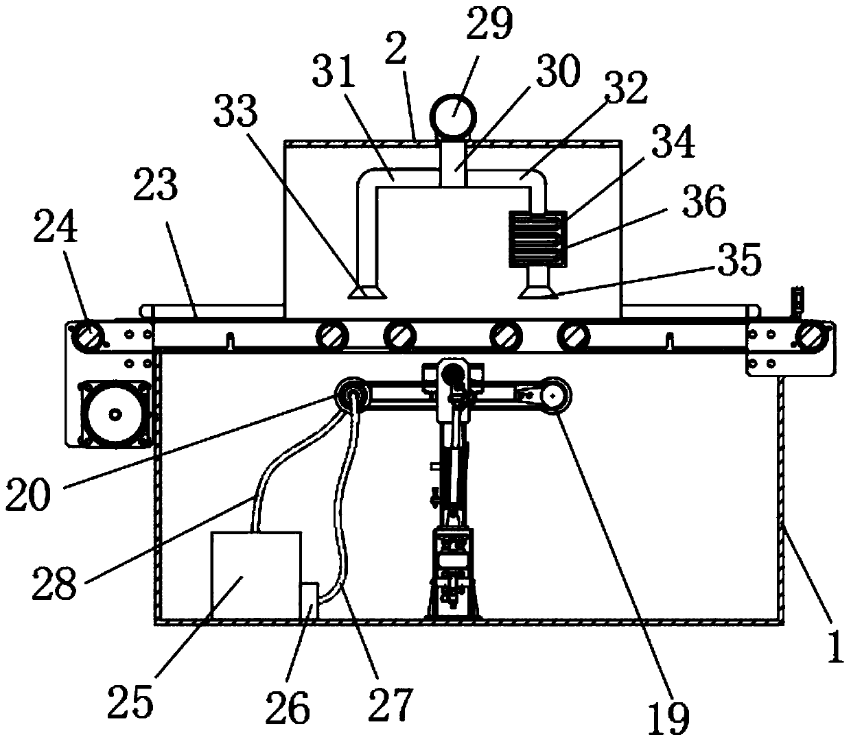
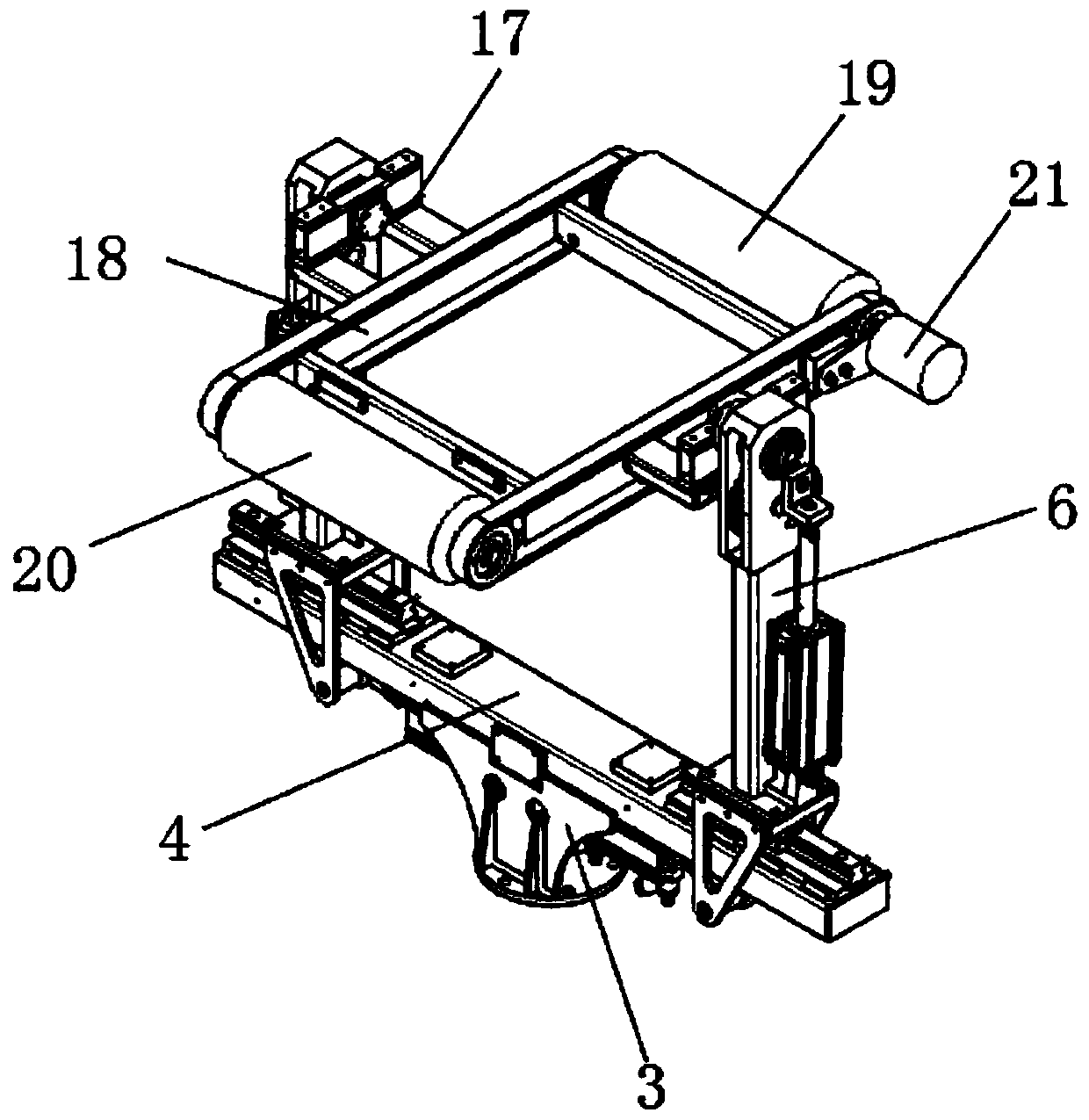
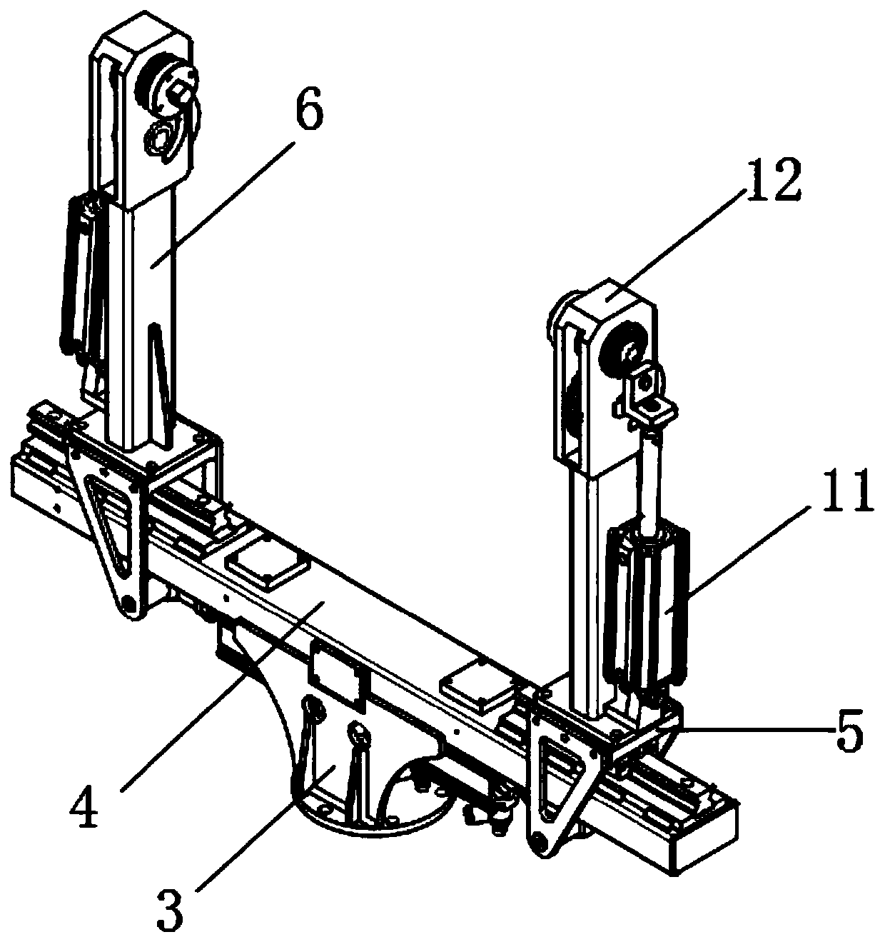
[0037] like Figure 1-8 As shown, a rapid cooling and drying mechanism of a vacuum aluminum coating machine includes a workbench 1, and a support base 3 is fixed by bolts at the middle position of the inner bottom wall of the workbench 1, and the top of the support base 3 is passed through A fixed strut 4 is fixedly installed by welding, and two sliding seats 5 are movably installed on the upper surface of the fixed strut 4. Both sides of the sliding seat 5 are vertically fixed with a first connecting plate 9 by bolts. The...


PUM


Abstract

The invention discloses a rapid cooling and drying mechanism of a vacuum aluminizing laminating machine and a cooling method thereof. The mechanism comprises a workbench, two sliding seats are movablymounted on the upper surface of a fixed supporting rod; supporting arms are fixedly mounted on the upper surfaces of the sliding seats; mounting chucks are fixed at the top ends of the supporting arms; a heating roller and a cooling roller are arranged between installation side plates, three conveying belts are arranged at the top of the workbench, a draught fan is fixedly installed at the top ofan installation housing, a first nozzle is fixedly installed at the bottom end of a first guide pipe, a heating box is fixedly installed at the bottom end of a second guide pipe, and a second spray head is fixedly installed at the bottom of the heating box. The cooling and drying mechanism is flexible, rapid and convenient to operate, capable of being switched back and forth between a drying modeand a cooling mode and reasonable in design; an aluminized product is dried and cooled at the same time in an air blowing mode and a roller contact mode, the drying and cooling effects are good, thedrying efficiency is improved, and continuous work of a cooling roller is achieved.

Description

technical field [0001] The invention relates to a cooling and drying mechanism, in particular to a rapid cooling and drying mechanism of a vacuum aluminum coating machine and a cooling method thereof. Background technique [0002] The laminating machine can be divided into two categories: the instant coating laminating machine and the pre-coating laminating machine. It is a special equipment for paper, board, and laminating film. , forming a paper-plastic product; [0003] The patent document (CN110721848A) discloses a film coating device on the surface of coated paper. The film coating device does not have a cooling function, and cannot switch back and forth between drying and cooling methods, and the drying method is single, and only one method is used for drying. The drying and cooling effect is poor, and the work efficiency is low. The cooling roller is easy to heat up after working for a long time. When the temperature of the device cannot be cooled, the cooling roller...

Claims


Application Information

Patent Timeline
Patent Type & Authority Applications(China)
IPC IPC(8): B32B37/08B32B38/16
CPCB32B37/08B32B38/164B32B2038/166
Inventor 李东霖桂茂生张先进
Owner ANHUI SHUNTONG PACKAGING MATERIAL
Why Eureka
Try Eureka