
Garbage liquid oil-water separation device

A technology of oil-water separation and garbage liquid, which is applied in the direction of liquid separation, immiscible liquid separation, and liquid separation through thermal diffusion, etc. It can solve the problems of burning garbage impurities, low heating efficiency and uniformity, and lack of stirring mechanisms, etc., to achieve Improve the stirring rate, facilitate cleaning and maintenance, and expand the effect of heat exchange area

Inactive Publication Date: 2020-08-18
江苏京泓生态环保有限公司
View PDF5 Cites 0 Cited by
  • Summary
  • Abstract
  • Description
  • Claims
  • Application Information

AI Technical Summary

Problems solved by technology

[0002] Traditional garbage liquid oil-water separation equipment adopts a cooling tower structure, and uses layered cooling surfaces to realize stepwise condensation and recovery of oil and water, but the oil-water separation structure of the layered structure cannot ensure sufficient separation of oil and water, and a certain degree of oil-water mixing still occurs; at the same time The traditional garbage oil-liquid separation equipment only heats and boils the garbage liquid, lacks the corresponding stirring mechanism, the heating efficiency and uniformity are low, and it is easy to produce garbage impurities

Method used


Image

  • Garbage liquid oil-water separation device

Examples


Embodiment Construction

[0020] The present invention is described in further detail now in conjunction with accompanying drawing. These drawings are all simplified schematic diagrams, which only illustrate the basic structure of the present invention in a schematic manner, so they only show the configurations related to the present invention.

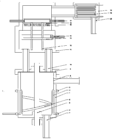
[0021] Such as figure 1 As shown, the present invention is a garbage liquid oil-water separation equipment, including a mixing tank, the wall of the mixing tank is provided with a number of inner grooves in an annular array, the bottom of the inner grooves protrudes toward the inside of the mixing tank, and the axis of the inner grooves is aligned with the axis of the mixing tank. Parallel, heat exchange tubes are inlaid in the inner grooves, and the two ends of the heat exchange tubes are respectively bent and provided with water inlet pipes and drain pipes, wherein the water inlet pipes of each inner groove heat exchange tubes are connected to a water inlet ...


PUM


Abstract

The invention relates to oil-water separation device for garbage liquid, which includes a stirring bucket, wherein a heating structure arranged in stirring bucket, heating residues and liquid in the stirring bucket, so that water and oil are evaporated; an exhaust pipe is arranged at the top of the stirring bucket, a cooling disc is arranged in the exhaust pipe, a water collecting disc is arrangedat the lower part of the cooling disc to recycle cooling liquid, a tail end cooling box is arranged at the tail end of the exhaust pipe, the bottom of the tail end cooling box is connected with an oil collecting pipe, and tail end steam is finally cooled in the tail end cooling box and recycled through the oil collecting pipe; a stirring shaft is coaxially and rotationally connected to the interior of the stirring bucket, a spiral stirring blade with the length being half of that of the stirring shaft is arranged on the stirring shaft, and one end of the spiral stirring blade is located at the bottom of the stirring bucket; the spiral stirring mechanism arranged in the structure lifts an object to a half height and then falls down, vertical turning of the material is achieved, uniform heating is guaranteed, and meanwhile it can be guaranteed that a high-temperature substance at the bottom can be moved to the surface of the material to be evaporated as soon as possible.

Description

technical field [0001] The invention relates to a garbage liquid oil-water separation device, which belongs to the field of environmental protection equipment. Background technique [0002] Traditional garbage liquid oil-water separation equipment adopts a cooling tower structure, and uses layered cooling surfaces to realize stepwise condensation and recovery of oil and water, but the oil-water separation structure of the layered structure cannot ensure sufficient separation of oil and water, and a certain degree of oil-water mixing still occurs; at the same time The traditional garbage oil-liquid separation equipment only heats and boils the garbage liquid for separation, lacks the corresponding stirring mechanism, the heating efficiency and uniformity are low, and it is easy to cause burning of garbage impurities. Contents of the invention [0003] The technical problem to be solved by the present invention is: to overcome the technical problems in the prior art and prov...

Claims


Application Information

Patent Timeline
Patent Type & Authority Applications(China)
IPC IPC(8): C02F1/04C02F1/40B01D17/09B01D17/02
CPCC02F1/048C02F1/04C02F1/043C02F1/40B01D17/02B01D17/005
Inventor 王子浩李重华张道兵舒俊赵志勇
Owner 江苏京泓生态环保有限公司
Learn More