
Process pipe with water cooled jackets at two ends

A process tube and water cooling technology, which is applied in the field of process tubes, can solve the problems of aging of the sealing ring, failure of the sealing ring, and low life expectancy, and achieve the effect of reducing the shutdown rate, increasing the output of the equipment and lowering the production cost.

Pending Publication Date: 2020-08-18
赛瑞达智能电子装备(无锡)有限公司
View PDF0 Cites 1 Cited by
  • Summary
  • Abstract
  • Description
  • Claims
  • Application Information

AI Technical Summary

Problems solved by technology

[0003] The object of the present invention is to provide a process tube with water cooling at both ends, to solve the problem in the above background technology that the heat conduction of the process tube must exist and cannot be isolated, so the entire annular surface of the sealing ring contacting the process tube is in a high temperature environment. Therefore, the sealing ring will quickly age and fail. Although it costs a lot to choose the material of the sealing ring to choose a material with high temperature resistance (the price of the material with high temperature resistance will be several times or ten times the price of ordinary sealing materials), but The service life is still low, because the failure of the sealing ring caused by the high temperature in the furnace and the heat transmitted to the sealing ring by the process tube cannot be solved

Method used


Image

  • Process pipe with water cooled jackets at two ends
  • Process pipe with water cooled jackets at two ends
  • Process pipe with water cooled jackets at two ends

Examples


Embodiment Construction

[0016] The following will clearly and completely describe the technical solutions in the embodiments of the present invention with reference to the accompanying drawings in the embodiments of the present invention. Obviously, the described embodiments are only some, not all, embodiments of the present invention. Based on the embodiments of the present invention, all other embodiments obtained by persons of ordinary skill in the art without making creative efforts belong to the protection scope of the present invention.

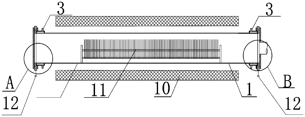
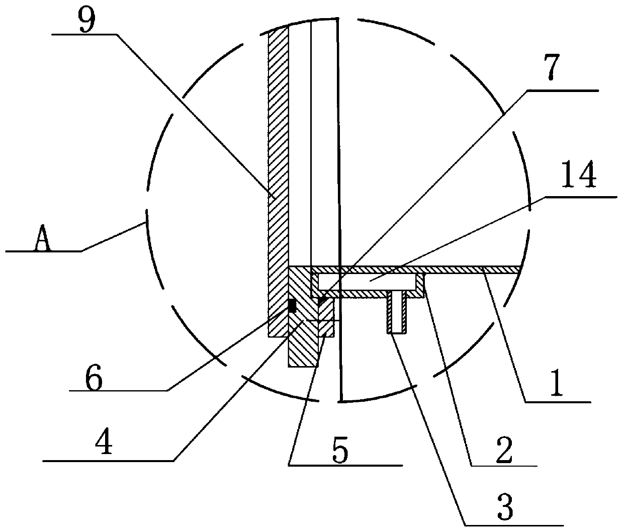
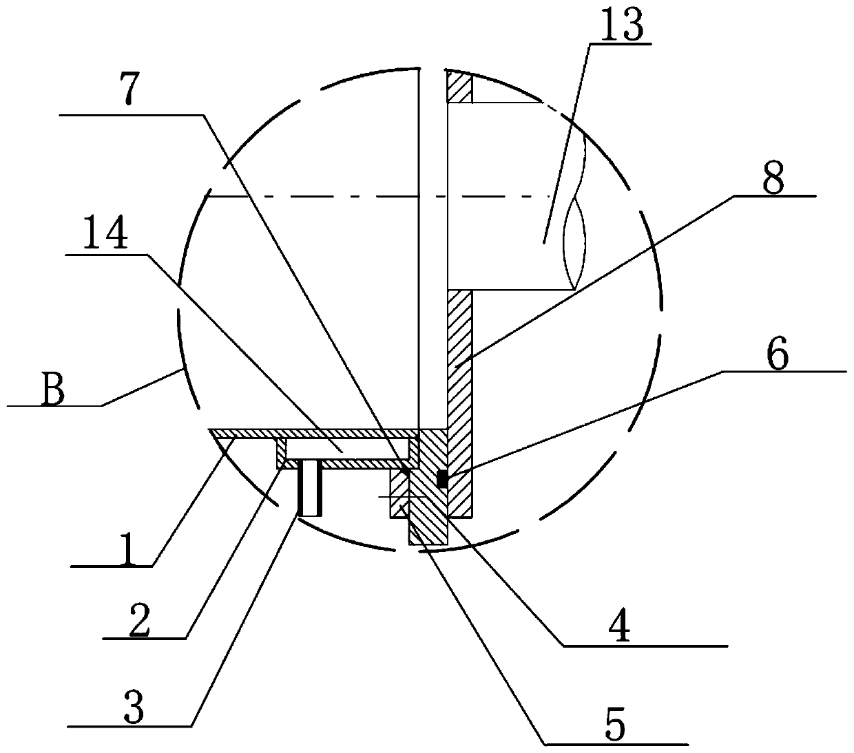
[0017] see Figure 1-3 , an embodiment provided by the present invention: a process tube with water cooling at both ends, including process tube main body 1, water cooling jacket 2, water inlet and outlet nozzle 3, front and rear fixing flanges 4, furnace door sealing ring 6, rear furnace door 8. Front furnace door 9, sheet boat and silicon wafer 11 and equipment frame body 12, the inner wall of equipment frame body 12 is fixedly installed with process pipe ma...


PUM


Abstract

The invention discloses a process pipe with water cooled jackets at two ends. The process pipe with the water cooled jackets at the two ends comprises a process pipe main body, the water cooled jackets, a water inlet and outlet nozzle, a back furnace door, a front furnace door, a sheet boat, a silicon wafer and an equipment rack body; the process pipe main body is fixedly mounted on the inner wallof the equipment rack body through front and back fixed flanges; and the water cooled jackets are fixedly mounted at the positions, near the equipment rack body, of the two ends of the process main body through the front and back fixed flanges. Through temperature of heat radiation generated by furnace mouths at two ends on the sealing position, the influence on a furnace door sealing ring as well as heat generated on the process pipe main body by a heater, cooling water inside flows rapidly to take away heat, so that heat influence on the furnace door sealing ring and a process pipe sealingring by heat conducted by the process pipe main body is blocked well, the temperature of the furnace door sealing ring and the process pipe sealing ring is maintained low, the sealing effect is guaranteed, and the service life of the furnace door sealing ring and the process pipe sealing ring is obviously prolonged.

Description

technical field [0001] The invention relates to the field of photovoltaic technology, in particular to a process tube with water cooling at both ends. Background technique [0002] The photovoltaic field is all in the form of tube furnace equipment (horizontal type). The way to protect the sealing ring of the furnace mouth is to set cooling water channels on the front and rear fixed flanges to cool the vicinity of the sealing ring to achieve the purpose. However, the sealing ring and the flange contact One side can have a cooling effect, but the side where the sealing ring contacts the process tube cannot be isolated due to the inevitable heat conduction of the process tube, so the entire annular surface of the sealing ring contacting the process tube is in a high temperature environment, so the sealing ring is very Fast aging and failure. Although it costs a lot to choose the material of the sealing ring and choose the material with high temperature resistance (the price of...

Claims


Application Information

Patent Timeline
Patent Type & Authority Applications(China)
IPC IPC(8): F27D9/00
CPCF27D9/00F27D2009/0013
Inventor 张海林刘国霞吴季浩
Owner 赛瑞达智能电子装备(无锡)有限公司
Learn More