
Part characteristic robot quick visual positioning method based on standard spherical array

A technology for parts features and visual positioning, applied in instruments, measuring devices, optical devices, etc., to achieve accurate positioning, simple and flexible methods, and a wide range of applications

Active Publication Date: 2020-08-18
HUAZHONG UNIV OF SCI & TECH
View PDF11 Cites 6 Cited by
  • Summary
  • Abstract
  • Description
  • Claims
  • Application Information

AI Technical Summary

Problems solved by technology

At the same time, the method uses a six-degree-of-freedom industrial robot to drive a raster-type binocular area scanner to scan and measure the standard spherical array and parts in an environmentally friendly manner to determine the spatial coordinates of the part features in the local coordinate system of the standard spherical array , in other locations with harsh environments, only by scanning the standard spherical array and creating a local coordinate system in the same way, the pose of the part features in space can be quickly located, and the present invention can perform rapid visual positioning of the part features with harsh service environments , which solves the problem of identifying and locating the features of parts with the naked eye, and has the advantages of strong practicability, high positioning accuracy, and wide application range, etc.

Method used


Image

  • Part characteristic robot quick visual positioning method based on standard spherical array
  • Part characteristic robot quick visual positioning method based on standard spherical array
  • Part characteristic robot quick visual positioning method based on standard spherical array

Examples


Embodiment Construction

[0037] In order to make the object, technical solution and advantages of the present invention clearer, the present invention will be further described in detail below in conjunction with the accompanying drawings and embodiments. It should be understood that the specific embodiments described here are only used to explain the present invention, not to limit the present invention. In addition, the technical features involved in the various embodiments of the present invention described below can be combined with each other as long as they do not constitute a conflict with each other.

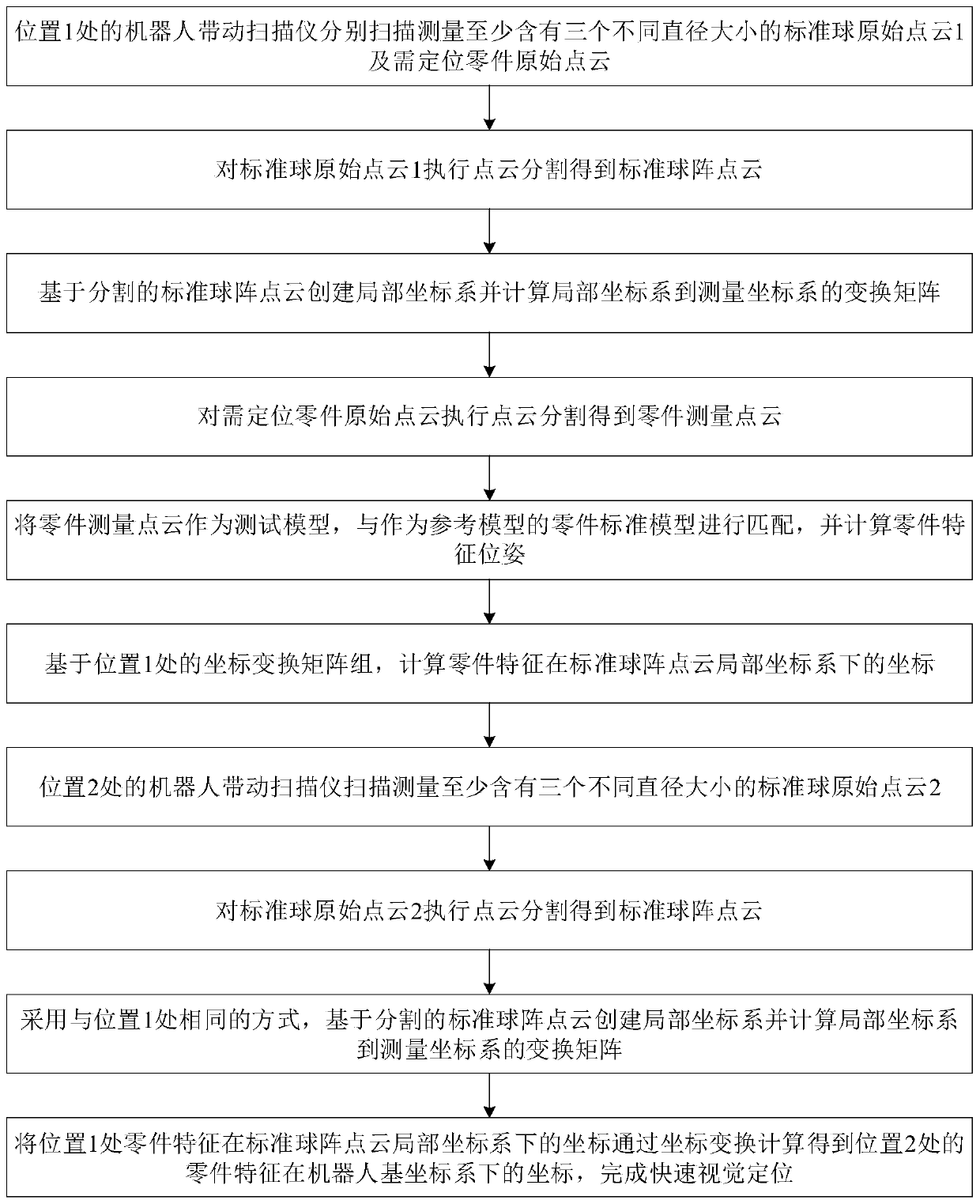
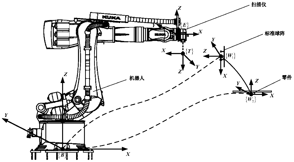
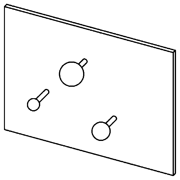
[0038] see figure 1 , figure 2 , image 3 , Figure 4 , Figure 5 and Figure 6 , the present invention provides a method for quickly visually locating part features based on standard ball arrays. The method is suitable for fast positioning of most part features. It adopts robot three-dimensional measurement technology and performs part features based on environment-friendly standard ball ...


PUM


Abstract

The invention belongs to the related technical field of automatic measurement and discloses a part characteristic robot quick visual positioning method based on a standard spherical array. The part characteristic robot quick visual positioning method is based on scanning a standard spherical array at a position 1, coordinates of part characteristics in a standard spherical array local coordinate system obtained through part calculation, and a local coordinate system created through scanning the standard spherical array at a position 2. The coordinates of part characteristics in space can be quickly positioned, and the robot is guided to complete mounting and dismounting of parts; wherein based on the obtained transformation matrix, coordinates of the part characteristics at the position 1under the standard spherical array point cloud local coordinate system are subjected to coordinate transformation calculation to obtain coordinates of the part characteristics at the position 2 underthe robot base coordinate system, and therefore quick visual positioning is completed. The method is high in applicability, the precision is greatly improved, and the application range is wide.

Description

technical field [0001] The invention belongs to the technical field related to automatic measurement, and more specifically, relates to a fast visual positioning method for a part feature robot based on a standard ball array. Background technique [0002] The determination of the characteristic pose of a part is an important prerequisite for the positioning, installation and disassembly of parts. In the field of intelligent manufacturing and equipment with robots as the main carrier, sensors and operating software are integrated to replace traditional human-eye recognition and positioning with visual positioning, and then the parts are analyzed and calculated. The pose of features in space has become one of the current research directions in the field of intelligent manufacturing and automated measurement. [0003] The service conditions of parts are often restricted by the surrounding environment, but when the parts are used in extremely harsh environments such as high temp...

Claims


Application Information

Patent Timeline
IPC IPC(8): G01B11/00
CPCG01B11/002
Inventor 李文龙田亚明王刚陈颖茂
Owner HUAZHONG UNIV OF SCI & TECH
Learn More