Uniform linear array low sidelobe beam forming optimization method under multiple constraints

A uniform linear array and optimization method technology, applied in radio wave measurement systems, radio wave reflection/reradiation, instruments, etc., can solve the problems of slow algorithm convergence, non-convergence, and failure to consider the requirements of array gain, etc., to achieve The array gain is large, the convergence speed is fast, and the convergence effect is good

Active Publication Date: 2020-08-18
UNIV OF ELECTRONICS SCI & TECH OF CHINA
View PDF6 Cites 17 Cited by
  • Summary
  • Abstract
  • Description
  • Claims
  • Application Information

AI Technical Summary

Problems solved by technology

However, this method does not take into account the requirements for array gain in actual engineering; at the same time, when the ADMM algorithm solves this type of optimization problem, the selection of the initial value of the penalty factor has a great influence on the convergence speed of the algorithm, and the algorithm is prone to slow or non-convergent convergence. Happening

Method used


Image

  • Uniform linear array low sidelobe beam forming optimization method under multiple constraints
  • Uniform linear array low sidelobe beam forming optimization method under multiple constraints
  • Uniform linear array low sidelobe beam forming optimization method under multiple constraints

Examples


Embodiment 1

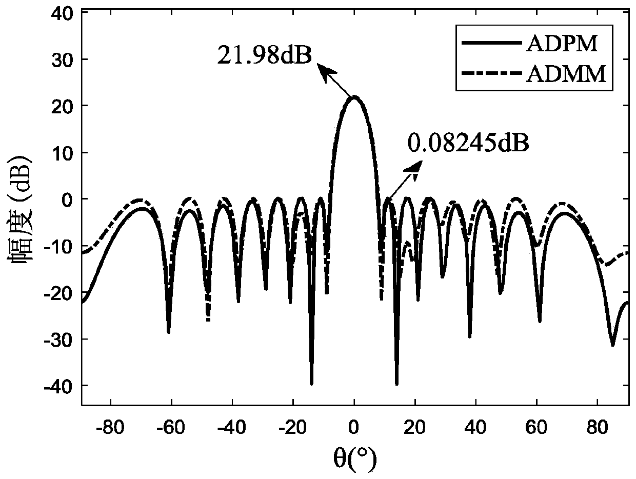
[0122] Embodiment 1: The number of uniform linear array elements is 16, the element interval is half a wavelength, the beam points to 0°, and the upper and lower bounds of the main lobe level are P l = 21.78dB and P u =21.98dB, the upper limit level of the side lobe level is η=0.083dB, and the lower limit of the weight amplitude range is σ=1 / 2 7 , the maximum number of iterations is K max =10000, the maximum tolerance is ε y =ε m =10 -5 , the initial value of the penalty factor is ρ y = ρ m =10 -4 , the value of the dual auxiliary variable does not exceed ν=500000, δ 1 =0.99, δ 2 =1.02, other parameters are initialized randomly between [0,1]. Considering that the noise covariance matrix is ​​R=I, the maximum array gain is 12.0411dB without other constraints. Compare the optimization effect of the ADPM algorithm that the present invention adopts and alternate direction multiplier (ADMM) algorithm, penalty factor is fixed as ρ y = ρ m =10 -4 , other conditions remai...

Embodiment 2

[0124] Embodiment 2: In order to analyze the performance advantages of the method of the present invention, different initial values ​​of penalty factors are set, and based on the above parameters, the convergence speeds of the two algorithms are compared.

[0125] Figure 7 is the penalty factor ρ y respectively set to ρ y =0.0001, ρ y = 0.001 and ρ y =0.01, the residual Δr corresponding to the two algorithms y the convergence curve; Figure 8 is the penalty factor ρ m respectively set to ρ m =0.0001, ρ m = 0.001 and ρ m =0.01, the residual Δr corresponding to the two algorithms m the convergence curve. from Figure 7 with Figure 8 It can be seen from the figure that setting different initial values ​​of the penalty factor has little influence on the convergence speed performance of the ADPM algorithm, and the convergence speed of the ADPM algorithm is faster when the same initial value of the penalty factor is set.

[0126] In summary, the multi-constrained uni...


PUM


Abstract

The invention discloses a uniform linear array low sidelobe beamforming optimization method under multiple constraints, is applied to the field of array signal processing, and aims to solve the problem that the selection of a penalty factor initial value greatly influences the convergence rate of an algorithm when an existing ADMM algorithm solves the optimization problem, and the situation of slow algorithm convergence or non-convergence is likely to occur. The method comprises the following steps: firstly, establishing a uniform linear array receiving signal model, taking array gain as a target function, considering main lobe level, side lobe level and weight amplitude constraints, then maximizing the array gain by adopting an alternating direction penalty algorithm, and solving an optimal array antenna weighting coefficient. Compared with an existing ADMM algorithm, the method is higher in convergence speed and better in convergence effect.

Description

technical field [0001] The invention belongs to the field of array signal processing, in particular to a uniform linear array low side lobe beam forming optimization technology under multiple constraints. Background technique [0002] Beamforming is a spatial filtering method that uses a set of sensors to enhance signals in the desired direction while suppressing interfering signals from different directions in space, so the optimization problem of beamforming has been extensively studied. The desired beam pattern obtained by designing the weighting coefficients of the array antenna usually focuses on the main lobe level and side lobe level, so as to achieve the suppression of interference signals from different directions outside the required direction in space; in addition, in practical engineering applications , the optimal design of the weighting coefficients of the array antenna needs to add the constraints of the weight range brought by the hardware devices, and consid...

Claims


Application Information

Patent Timeline
Patent Type & Authority Applications(China)
IPC IPC(8): G01S13/02G01S7/40
CPCG01S13/02G01S7/4004G01S2013/0245
Inventor 崔国龙路晴辉刘瑞涛徐彦钦余显祥郭世盛孔令讲
Owner UNIV OF ELECTRONICS SCI & TECH OF CHINA
Why Eureka
Try Eureka