Electric grounding pile for electric power engineering

A technology of electric power engineering and grounding piles, which is applied in the field of electric power grounding piles for electric power engineering, which can solve the problems of hidden dangers in line safety operation, easy to be pulled out by external force, high maintenance cost, etc., achieve good fixing effect, not easy to pull out, and reduce maintenance cost effect

Active Publication Date: 2020-08-18
国网河南省电力公司鄢陵县供电公司
5 Cites 1 Cited by

AI-Extracted Technical Summary

Problems solved by technology

[0002] Power transmission lines and related equipment are mostly located outdoors, and are prone to lightning strikes. Line trips caused by lightning strikes often occur. In order to prevent lightning strikes, it is necessary to install grounding devices for transmission lines to guide the current generated by lightnin...

Abstract

The invention discloses an electric grounding pile for electric power engineering. The grounding pile comprises a grounding pile body, a cavity, a plug, a push rod, an accommodating groove, a rotatingshaft, a gear, a groove, a spring, a limiting plate, a rack plate and an elastic plate. The cavity is arranged in the grounding pile body, the top end of the grounding pile body is provided with theplug, and a wiring hole is formed in the plug. The push rod is arranged in the cavity, the accommodating groove is formed on the inner side wall of the cavity, and the rotating shaft is fixedly arranged in the accommodating groove and is rotatably connected with the gear. The rack plate is fixedly arranged on the push rod, a groove with an opening at the bottom end is formed at the top end of thecontaining groove, and the spring is fixedly connected to the side wall of the groove. The other end of the spring is fixedly connected with the limiting plate, the other side face of the limiting plate is closely connected with the side wall of the groove, and the bottom end of the limiting plate extends between every two adjacent meshing teeth and is hinged to the elastic plate. In general, theelectric grounding pile has the advantages of being firm in fixation, being not prone to being pulled out and being capable of reducing the maintenance cost.

Application Domain

Connection contact member material

Technology Topic

Power engineeringRack and pinion +3

Image

  • Electric grounding pile for electric power engineering
  • Electric grounding pile for electric power engineering
  • Electric grounding pile for electric power engineering

Examples

  • Experimental program(1)

Example Embodiment

[0022] The technical solution of the present invention will be further specifically described below in conjunction with the drawings.
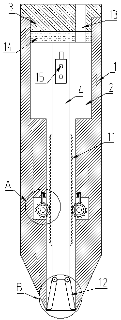
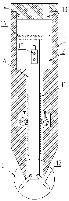
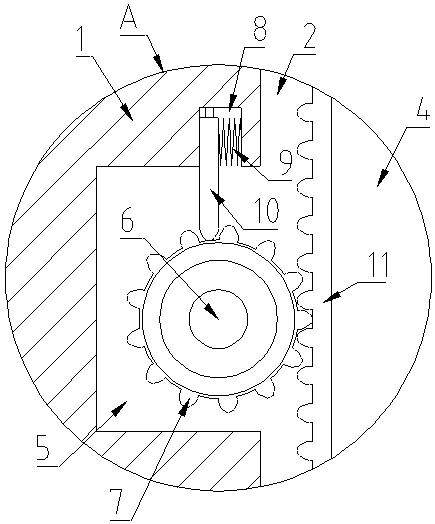
[0023] Such as figure 1 , figure 2 , image 3 , Figure 4 , Figure 5 As shown, a power grounding pile for power engineering includes a grounding pile body 1, a cavity 2, a plugging head 3, a push rod 4, an accommodation groove 5, a rotating shaft 6, a gear 7, a groove 8, a spring 9, and a limiter. Bit plate 10, rack plate 11 and elastic plate 12.
[0024] Wherein, the bottom of the grounding pile body 1 can be set to have an inverted conical structure, and the grounding pile body 1 is provided with a cylindrical cavity 2 passing through its height direction. The cavity 2 can also be set from top to bottom. The stepped cylindrical structure with the lower diameter sequentially reduced is convenient for limiting the position. The plugging head 3 is provided on the top of the grounding pile body 1, and the plugging head 3 is provided with a wiring hole 13 penetrating through its thickness direction. The cavity 2 is provided with a push rod 4, the upper part of the push rod 4 is fixedly connected with a wiring tube 15, the top of the push rod 4 is provided with a moving plate 14, and the moving plate 14 is provided with a wiring hole 13, And the wiring hole 13 communicates with the wiring hole 13 on the plug 3, and the two wiring holes 13 are arranged coaxially. The movable plate 14 is slidably arranged in the cavity 2, and the movable plate 14 is A sliding block is provided on the side surface where the inner side wall of the cavity 2 is in contact, and a sliding groove is arranged on the side wall of the cavity 2, and the movable plate 14 and the cavity 2 are slidably connected up and down through the sliding block and the sliding groove. The moving plate 14 is arranged in the upper half of the stepped cylindrical cavity 2. The steps inside the cavity 2 can limit the up and down movement of the moving plate 14. The lower part of the inner side wall of the cavity 2 is provided with The opening faces the accommodating groove 5 inside the cavity 2. A rotating shaft 6 is fixedly arranged in the accommodating groove 5, the rotating shaft 6 is rotatably connected with the gear 7, and the meshing teeth of the gear 7 face the cavity 2 , The push rod 4 is fixedly provided with a rack plate 11 meshingly connected with the gear 7, and the top of the containing groove 5 is provided with a groove 8 with an open bottom end, and the groove 8 is close to the side of the cavity 2 A transversely arranged spring 9 is fixedly connected to the wall, the other end of the spring 9 is fixedly connected to the limiting plate 10, and the other side of the limiting plate 10 is closely connected to the side wall of the groove 8 away from the cavity 2, and The bottom end of the limiting plate 10 extends between two adjacent meshing teeth, the top wall of the groove 8 is provided with a sliding groove, the top of the limiting plate 10 is provided with a slider, and the limiting plate 10 and the top wall of the groove 8 are slidably connected to the left and right through a sliding groove and a sliding block. The bottom end of the push rod 4 is hinged with the elastic plate 12, and the elastic plate 12 can be set in two, which are respectively hinged on the push rod. Both sides of the bottom end of the rod 4 are distributed in a roughly figure eight shape. A spring 9 can be fixed between the two elastic plates 12, and the bottom end of the elastic plate 12 can be a cone-shaped structure for easy penetration. In the soil.
[0025] In the specific implementation of the present invention, when the plugging head 3 is provided at the top of the grounding pile body 1, the push rod 4 and the grounding pile body 1 are driven down synchronously by external force. After the grounding pile body 1 penetrates the ground, the plugging is removed The head 3 strikes the push rod 4 again with an external force, so that the push rod 4 moves downward, the rack plate 11 on the push rod 4 meshes with the gear 7, and the gear 7 rotates in the positive direction, ie image 3 As shown in the figure, the meshing teeth on the gear 7 positively push the limit plate 10, and the limit plate 10 moves in the direction of the cavity in the groove 8, compressing the spring 9 until the current meshing tooth is out of the limit position. After the limit of the plate 10, the limit plate 10 loses the thrust given by the current meshing tooth, the spring 9 drives the limit plate 10 to return to the original position, the next meshing tooth repeatedly pushes the limit plate 10 positively, and when the gear 7 performs When rotating in the opposite direction, that is, as image 3 As shown in the figure, when rotating counterclockwise, the meshing tooth exerts a reverse thrust on the limit plate 10, and the groove 8 is far away from the side wall of the cavity to limit the limit plate 10, and the two fit more closely. The bit plate 10 blocks the movement of the meshing teeth, and the gear 7 cannot rotate, which can effectively prevent the gear 7 from rotating in the opposite direction, thereby preventing the push rod 4 from moving upwards and being pulled out; the push rod 4 moves downwards to drive the elastic plate 12 to move downwards, elastic The plate 12 loses the restraint of the side wall of the cavity 2 and moves to the two sides of the grounding pile body 1 under the thrust of the spring 9 and is inserted into the soil to form a roughly eight-shaped structure, which can further fix the grounding pile body 1 , The fixing effect is better, it can effectively avoid the theft of the grounding stake and reduce the maintenance cost.
[0026] The above are only the preferred embodiments of the present invention, and are not intended to limit the present invention. Any modification, equivalent replacement, improvement, etc. made within the spirit and principle of the present invention shall be included in the protection of the present invention. Within range.

PUM

no PUM

Description & Claims & Application Information

We can also present the details of the Description, Claims and Application information to help users get a comprehensive understanding of the technical details of the patent, such as background art, summary of invention, brief description of drawings, description of embodiments, and other original content. On the other hand, users can also determine the specific scope of protection of the technology through the list of claims; as well as understand the changes in the life cycle of the technology with the presentation of the patent timeline. Login to view more.

Similar technology patents

Capacitor assembly welding tool

InactiveCN102990262AGood fixed effectlow cost
Owner:GLORYMV ELECTRONICS

Hemodialysis upper limb fixing device

Owner:CHENGDU KECHUANG JIASI TECH

Tire torque measuring instrument

Owner:CHANGZHOU DERI MACHINERY

Classification and recommendation of technical efficacy words

  • Good fixed effect
  • prevent theft

Auxiliary supporting frame for ophthalmology department doctor operation

ActiveCN108938301AGood fixed effectAvoid affecting the results of surgery
Owner:THE THIRD AFFILIATED HOSPITAL OF XINXIANG MEDICAL UNIV

Drawing board for environmental art design

InactiveCN109484063AGood fixed effectImprove drawing efficiency
Owner:安陆风常建筑景观规划设计有限公司
Why Eureka
Try Eureka