Protection structure of inverter device for electric vehicle
A protection structure and inverter technology, which can be applied to the structural parts of conversion equipment, modification of power electronics, and output power conversion devices, etc., can solve problems such as small protection range, shortened service life, and inverter damage, etc. Achieve the effect of improving heat dissipation efficiency, easy clamping and fixing, easy disassembly and stability
- Summary
- Abstract
- Description
- Claims
- Application Information
AI Technical Summary
Problems solved by technology
Method used
Image
Examples
Embodiment 1
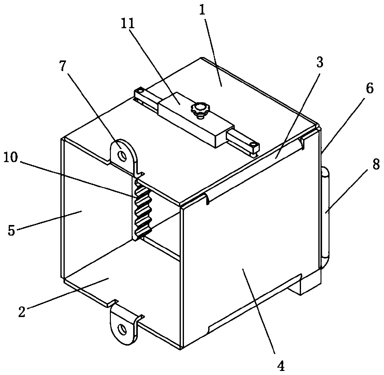
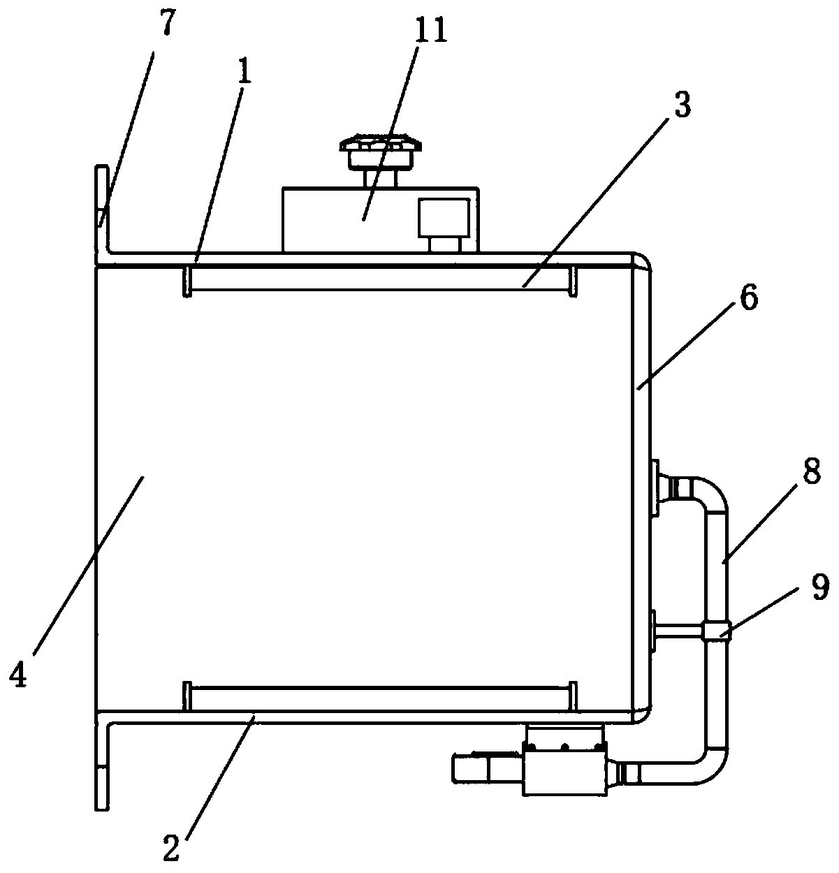
[0030] see Figure 1-2 As shown, the present invention provides a protective structure for an inverter device for an electric vehicle through improvement, including a top cover plate 1, a bottom plate 2, an arc connector 3, a right side plate 4, a left side plate 5, a rear seal Plate 6, external fixing ring 7, heat dissipation device 8, fixing structure 9, bidirectional clamping mechanism 10 and synchronous pushing mechanism 11, the top cover plate 1 and the bottom plate 2 are symmetrically arranged up and down, and the two sides are symmetrical to the left and right through the arc connector 3 The set right side plate 4 is connected with the left side plate 5, and forms a rectangular cavity structure through the back cover plate 6 at the rear end, which is used for embedded installation of the inverter and protects the inverter. The top cover plate 1 and the bottom plate 2 The upper and lower sides of the front end are provided with external fixing rings 7 in an arc-shaped st...
Embodiment 2
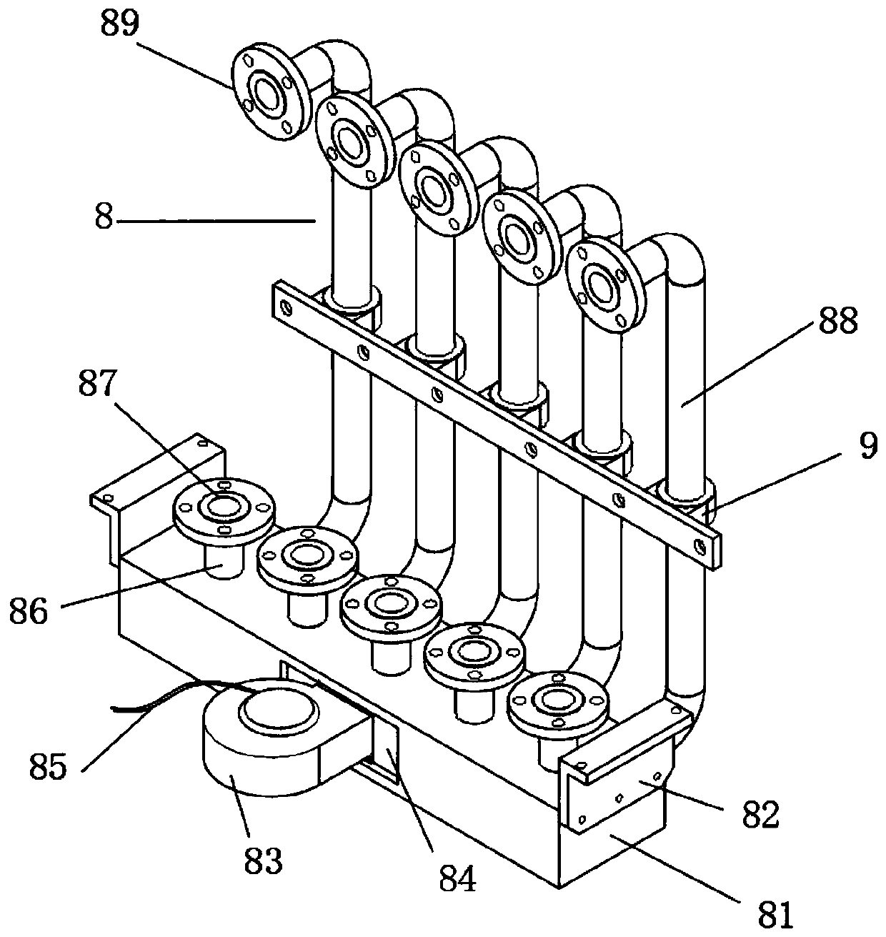
[0036] The present invention provides a protective structure for an inverter device for an electric vehicle by improving the protection structure. The air outlet of the blower 83 is communicated with the inside of the air collecting box 81 , so that the wind delivered by the blower 83 can enter into the air collecting box 81 after the blower 83 works. The first air transmission pipe 86 is communicated with the upper end of the air collecting box body 81, so that the wind power collected in the air collecting box body 81 can be transported to the bottom plate 2 through the first air transmission pipe 86, and the second air conveying pipe 88 is connected to the collecting box body 81. The rear and middle parts of the air box body 81 are connected, so that the wind power collected in the air collecting box body 81 can be transported to the rear sealing plate 6 through the second air supply pipe 88. Rubber pads 93 are provided in the five pipe sleeves 92, which is convenient for To...
PUM
 Abstract
Description
Claims
Application Information
 - R&D
- Intellectual Property
- Life Sciences
- Materials
- Tech Scout
- Unparalleled Data Quality
- Higher Quality Content
- 60% Fewer Hallucinations
Browse by: Latest US Patents, China's latest patents, Technical Efficacy Thesaurus, Application Domain, Technology Topic, Popular Technical Reports.
© 2025 PatSnap. All rights reserved.Legal|Privacy policy|Modern Slavery Act Transparency Statement|Sitemap|About US| Contact US: help@patsnap.com


