
Reciprocating type polishing device for stainless steel pipe machining and method

A technology of polishing device and stainless steel tube, which is applied to grinding drive device, metal processing equipment, grinding/polishing equipment, etc., can solve the problems of low efficiency, multiple human resources, consumption, etc., so as to improve processing efficiency and polishing efficiency. , Reasonable effect of structural design

Active Publication Date: 2020-08-21
湖州中锐洁净科技有限公司
View PDF10 Cites 9 Cited by
  • Summary
  • Abstract
  • Description
  • Claims
  • Application Information

AI Technical Summary

Problems solved by technology

[0004] The purpose of the present invention is to solve the problem that the existing stainless steel pipe polishing work is not only inefficient, but also consumes more human resources, and proposes a reciprocating polishing device and method for stainless steel pipe processing, which can realize It has the effect of fully limiting and tightening the workpiece to be processed, and realizes the rotation of the workpiece to be processed. While realizing automatic polishing, it can improve processing efficiency and reduce the consumption of human resources.

Method used


Image

  • Reciprocating type polishing device for stainless steel pipe machining and method
  • Reciprocating type polishing device for stainless steel pipe machining and method
  • Reciprocating type polishing device for stainless steel pipe machining and method

Examples


Embodiment Construction

[0026] The following will clearly and completely describe the technical solutions in the embodiments of the present invention with reference to the accompanying drawings in the embodiments of the present invention. Obviously, the described embodiments are only some, not all, embodiments of the present invention.

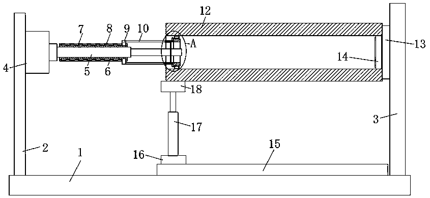
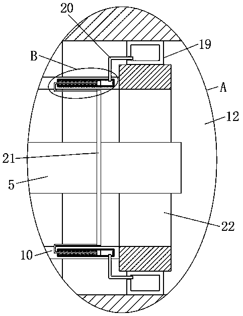
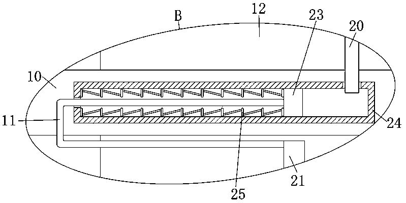
[0027] refer to Figure 1-3 , a reciprocating polishing device for stainless steel pipe processing, including a base 1, the upper end of the base 1 is vertically provided with a first support plate 2 and a second support plate 3, and the first support plate 2 is close to one end side of the second support plate 3 The wall is provided with a support rotation mechanism, the support rotation mechanism includes a motor 4 fixed on the side wall of the first support plate 2, the end of the output shaft of the motor 4 is fixedly connected with the first electric push rod 5, and the fixed end of the first electric push rod 5 Both the upper and lower sides are provided with m...


PUM


Abstract

The invention discloses a reciprocating type polishing device for stainless steel pipe machining. The device comprises a base, a first supporting plate and a second supporting plate are vertically arranged at the upper end of the base, a supporting rotating mechanism is arranged on the side wall of the end, close to the second supporting plate, of the first supporting plate, the end, close to thefirst supporting plate, of the second supporting plate is fixedly connected with a limiting mechanism, a to-be-machined workpiece is arranged between the first supporting plate and the second supporting plate, the supporting rotating mechanism and the limiting mechanism extend into the to-be-machined workpiece and abut against the inner side wall of the to-be-machined workpiece, a machining mechanism abutting against the side wall of the workpiece to be machined is arranged at the upper end of the base, and the supporting rotating mechanism comprises a motor fixed to the side wall of the firstsupporting plate. According to the device, the structural design is reasonable, the to-be-machined workpiece can be fully limited and abutted against, and the to-be-machined workpiece can be rotated,so that the automatic polishing work is achieved, and meanwhile, the machining efficiency can be improved, and the consumption of human resources can be reduced.

Description

technical field [0001] The invention relates to the technical field of stainless steel tube processing, in particular to a reciprocating polishing device and method for stainless steel tube processing. Background technique [0002] In recent years, the market demand for stainless steel pipes has been continuously increasing. Stainless steel pipe fittings have good mechanical properties and corrosion resistance, and are widely used in aerospace, marine, nuclear energy, medical equipment and petrochemical fields. At the same time, stainless steel pipes have good corrosion resistance. It can be used in fluid conveying pipelines of high-end products. [0003] During the production process of stainless steel pipes, the outer wall of the stainless steel pipe needs to be polished and polished. At present, most of them are polished by hand-held sandpaper, which is not only inefficient, but also requires more human resources. Therefore, we have designed a reciprocating polishing dev...

Claims


Application Information

Patent Timeline
Patent Type & Authority Applications(China)
IPC IPC(8): B24B1/00B24B5/04B24B5/35B24B29/08B24B41/06B24B47/12B24B47/22B24B41/02
CPCB24B1/00B24B5/045B24B5/35B24B29/08B24B41/02B24B41/06B24B47/12B24B47/22
Inventor 李洪伟
Owner 湖州中锐洁净科技有限公司
Learn More