
A sound-absorbing structure for an air supply duct of a rail vehicle

A technology for rail vehicles and air supply ducts, which is applied in the field of rail vehicle air conditioning systems, can solve the problems that the air ducts are not silenced or soundproofed, are not suitable for occasions with high sound requirements, and the wind fluctuates with large noise, achieving obvious effects and reducing the cost , the effect of reducing the vibration effect

Active Publication Date: 2021-06-22
安徽浦进轨道装备有限公司
View PDF1 Cites 0 Cited by
  • Summary
  • Abstract
  • Description
  • Claims
  • Application Information

AI Technical Summary

Problems solved by technology

[0004] In the existing air supply mode, the installation position of the fan is usually very close to the driver's cab, and the air supply port is located on the axis of the fan outlet, and the wind speed is high. After the sound wave enters the air duct, it is directly transmitted to the cab along the air duct. The duct is not sound-proof and sound-proof, and the wind fluctuates and the noise is relatively large, so it is not suitable for occasions with high sound requirements. At the same time, the use of this air duct requires the installation of a large number of mufflers, which increases the total cost of the project.

Method used


Image

  • A sound-absorbing structure for an air supply duct of a rail vehicle
  • A sound-absorbing structure for an air supply duct of a rail vehicle
  • A sound-absorbing structure for an air supply duct of a rail vehicle

Examples


Embodiment 1

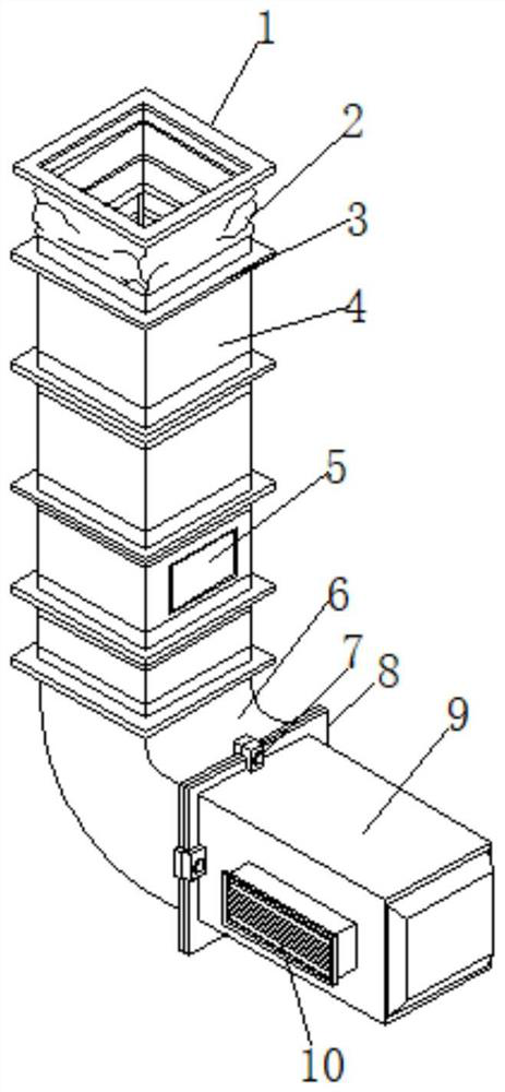
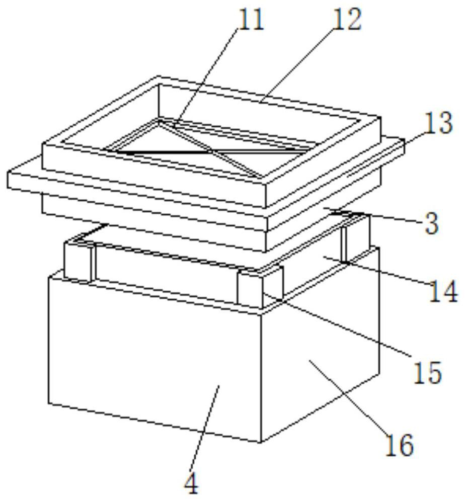
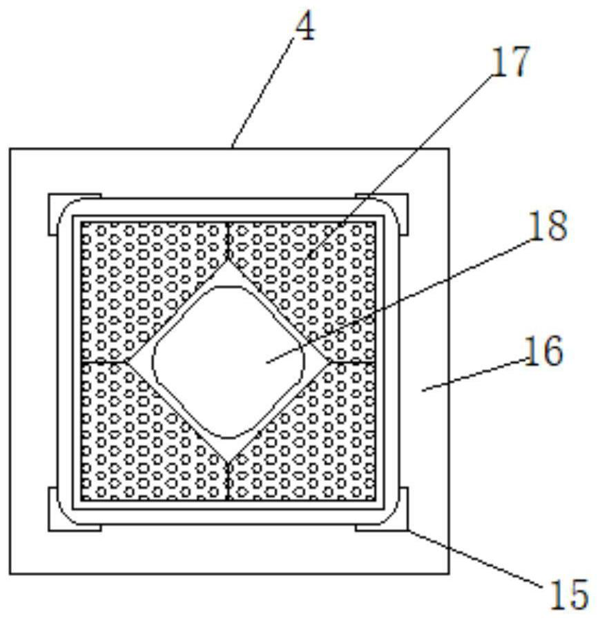
[0028] refer to Figure 1-4 , a rail vehicle air supply channel noise reduction structure, including an air inlet flange 1, the outer wall of the bottom end of the air inlet flange 1 is socketed with a flexible pipe 2, and the outer wall of the bottom end of the flexible pipe 2 is socketed with a connecting flange 3 , the outer wall of the bottom end of the connecting flange 3 is sleeved with an air duct pipe 4, and the number of the air duct pipe 4 is at least two, and the opposite ends of the two air duct pipes 4 are fixed by the connecting flange 3, and the air duct The outer wall of the bottom end of the duct 4 is connected with a connecting elbow 6, and the end of the connecting elbow 6 is provided with a pressing flange 8, and the connecting elbow 6 is fixedly connected with an air outlet pipe 9 through the pressing flange 8, and the air outlet pipe 9 The middle part of one side of the outer wall is provided with an air outlet fan 10, and the middle part of one side of t...

Embodiment 2

[0031] refer to Figure 5 , a rail vehicle air supply duct noise reduction structure, the main difference between this embodiment and embodiment 1 is that in this embodiment, it also includes a frequency sensor 23, an electromagnetic driver 22 and a vibrating membrane 21, and the frequency sensor 23 is fixedly connected to the outlet The air duct 9 is close to the inner wall of one end of the pressing flange 8, and the output end of the electromagnetic driver 22 is fixedly connected to the outer wall of one side of the vibrating membrane 21, and the other side of the vibrating membrane 21 is arranged on the inner wall of the end of the cavity. Both the driver 22 and the blower fan 10 are connected with a switch, and the switch is connected with a PLC controller through wires.

[0032]The working principle of this embodiment: based on the working principle in Embodiment 1, wherein an active interference device is provided in the air outlet pipe, the frequency sensor 23 senses t...


PUM


Abstract

The invention discloses a sound-absorbing structure for an air supply channel of a rail vehicle, which comprises an air inlet flange, a flexible connecting pipe is socketed on the outer wall of the bottom end of the air inlet flange, and a connecting flange is socketed on the outer wall of the bottom end of the flexible connecting pipe , the outer wall of the bottom end of the connecting flange is sleeved with air duct pipes, and the number of air duct pipes is at least two, and the opposite ends of the air duct pipes in pairs are fixed by connecting flanges, and the air duct A connecting elbow is connected to the outer wall of the bottom end of the pipe, and the end of the connecting elbow is provided with a pressing flange, and the connecting elbow is fixedly connected with an air outlet pipe through the pressing flange. The pipe wall of the wind pipe lining plate in the present invention is a porous sound-absorbing material. With the extension of the pipe, the sound-absorbing effect is more obvious. The C-shaped groove is clamped and fixed, and the air duct pipe is changed at both ends to control the wind speed. A cavity is formed between the diameter-reducing bucket and the air duct pipe body, which has a sound insulation effect.

Description

technical field [0001] The invention relates to the technical field of rail vehicle air conditioning systems, in particular to a rail vehicle air supply duct noise reduction structure. Background technique [0002] The traditional form of the air-conditioning air supply duct of the rail vehicle driver's cab is generally a straight-through structure with a rectangular cross-section. The air inlet and outlet are respectively located at both ends of the air supply duct. The vents are connected. [0003] For example, the authorized announcement number is CN203391778U, which discloses a rail vehicle driver's cab air supply channel noise reduction structure, which has an air supply channel arranged along the direction of the vehicle, the rear end of the air supply channel is connected to the air outlet of the air conditioner, and the inside of the air supply channel is close to its front end. A micro-orifice plate is arranged horizontally at the position, and a plenum is formed b...

Claims


Application Information

Patent Timeline
Patent Type & Authority Patents(China)
IPC IPC(8): B61D27/00B61C17/04F24F13/24
CPCB61C17/04B61D27/009F24F13/24F24F2013/242F24F2013/245F24F2013/247
Inventor 许超
Owner 安徽浦进轨道装备有限公司
Learn More