Stress safety judgment method for layered pouring concrete first-layer beam

A concrete beam, layered pouring technology, applied in bridges, buildings, bridge construction, etc., can solve problems affecting the safety and durability of concrete, reduce the corrosion resistance of structures, reduce the strength and stability of concrete beams, and save later Operation and maintenance funds, significant economic and social benefits, and the effect of simple and easy procedures

Active Publication Date: 2020-08-21
GUANGXI TRANSPORTATION SCI & TECH GRP CO LTD +1
View PDF8 Cites 2 Cited by
  • Summary
  • Abstract
  • Description
  • Claims
  • Application Information

AI Technical Summary

Problems solved by technology

For cast-in-place brackets, especially for concrete beams that are supported by full brackets and poured in layers, the poor shrinkage of the layered concrete, the settlement of the brackets, the temperature drop of concrete hydration, and the construction process will cause the concrete to appear. Cracks will accelerate the carbonation of concrete and reduce the corrosion resistance of the structure, eventually reducing the strength and stability of concrete beams, which will reduce the service life of structures and seriously affect the safety and durability of concrete
For cast-in-place brackets, especially for concrete beams that are supported by brackets and cast in layers, there are often excessive stresses on the beams in the early stage that cause concrete cracking, safety and durability problems. There is no relevant literature report on the research and analysis of the safety status of the first-story concrete beams, so there is an urgent need for a method to judge the safety of the first-story beams of cast-in-place concrete beams.

Method used


Image

  • Stress safety judgment method for layered pouring concrete first-layer beam
  • Stress safety judgment method for layered pouring concrete first-layer beam
  • Stress safety judgment method for layered pouring concrete first-layer beam

Examples


Embodiment

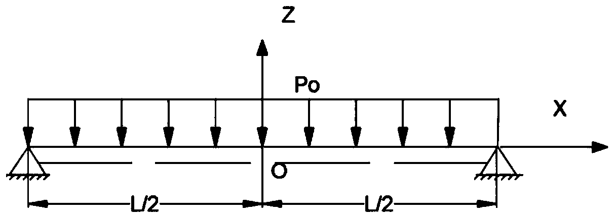
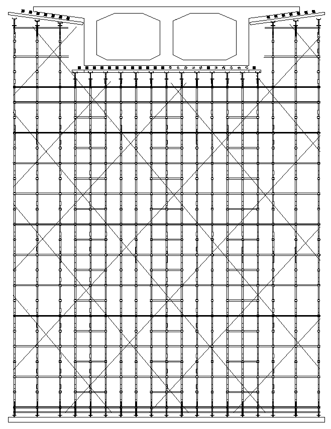
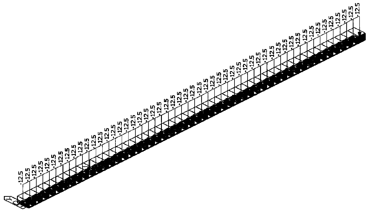
[0081] Take a simply supported girder bridge as an example, the minimum height of the clearance under the bridge is 6.0 meters, the vehicle load level is road-level I, the maximum height of the support is 6.8m, and the maximum height of the support is 16m. Vertical pole cross-bridge spacing × vertical pole vertical bridge spacing x cross-bar step distance is 60cm × 60cm × 120cm, and the bracket is set on the strip foundation Spiral steel pipe, as follows Figure 4 shown. The pouring height of the first stage is 500mm, and when the first floor beam is a simply supported beam, the pouring height of the first floor should account for 0.3-0.7 of the total height, and the pouring height of the second stage is 500mm, and the priority is given to setting the construction joints near the neutral axis, and dividing the construction joints Finally, the second-floor pouring layer is equivalent to a support system that transmits uniformly distributed loads to the first floor.

[0082] ...


PUM


Abstract

The invention relates to the field of bridge and culvert engineering in the transportation industry, and particularly discloses a stress safety judgment method for a layered pouring concrete first-layer beam. Layered pouring concrete beams constructed by adopting a full framing are generally and reasonably poured layer by layer along the height of beams. Based on an elastic mechanics theory, the method comprises the following steps of deducing a stress function on the first-layer concrete beam when second-layer concrete is poured; determining the stress safety value of the first-layer concretebeam according to the compressive strength test value of the cubic concrete test blocks of the same batch of the first-layer concrete beam, thereby saving a large amount of time required by finite element analysis in the construction process; rapid judgment of stress safety, process simplicity and feasibility, the construction safety of the cast-in-place concrete beam of the bracket can be guaranteed; the risk that the durability of the bridge is affected by fracture or cracks of the concrete beam due to overlarge stress in the pouring process is avoided, the long-term service safety performance of the concrete beam is guaranteed, the later operation and maintenance funds are saved, and very remarkable economic and social benefits are achieved.

Description

technical field [0001] The invention relates to the field of bridge and culvert engineering in the transportation industry, in particular to a method for judging the force safety of a first-story beam of concrete poured in layers. Background technique [0002] Concrete bridges are widely used in bridge construction due to their good mechanical performance, serviceability and construction maturity. Most of the concrete beams are not casted in one time, especially the concrete beams with high beam height or complex detailed structure, generally need to be poured multiple times. For cast-in-place brackets, especially for concrete beams that are supported by full brackets and poured in layers, the poor shrinkage of the layered concrete, the settlement of the brackets, the temperature drop of concrete hydration, and the construction process will cause the concrete to appear. Cracks accelerate the carbonation of concrete and reduce the corrosion resistance of the structure, and u...

Claims


Application Information

Patent Timeline
Patent Type & Authority Applications(China)
IPC IPC(8): G06F30/23G06F30/13G06F17/13E01D21/00G06F119/14E01D101/26
CPCG06F30/23G06F30/13G06F17/13E01D21/00G06F2119/14E01D2101/26
Inventor 姚鑫玉刘展瑞周冬明王华卓小丽伍钧鸿
Owner GUANGXI TRANSPORTATION SCI & TECH GRP CO LTD
Why Eureka
Try Eureka