Intelligent wardrobe and control method thereof

A control method and technology for wardrobes, which are applied in the directions of wardrobes, cabinets, sanitary equipment for toilets, etc., can solve the problems of lack of safety equipment, unsatisfactory effects, and hidden safety hazards, and achieve high safety performance, strong practicability, and high flexibility. Effect

Inactive Publication Date: 2020-08-25
北京博纳菲德科技有限公司
5 Cites 0 Cited by

AI-Extracted Technical Summary

Problems solved by technology

[0003] But because the wardrobe in the prior art only has the effect of storing clothes in general, and the structure is simple, there is no corresponding safety equipment, and the opening method is to open directly, when in an unsafe environment, then there is a certain potential safety hazard, and secondly, if When dehumidification or steri...

Method used

The present invention provides a kind of intelligent wardrobe and the control method of intelligent wardrobe, by arranging intelligent door lock and face recognition system, face recognition system can be connected to server terminal by communication simultaneously, and the user can be remote to wardrobe interior through server terminal Observe the temperature and humidity, the storage of clothes and the smoke situation, and issue corresponding instructions to adjust the internal situation. The degree of intelligence is higher, and there is no need for staff to observe in person, saving time and effort. The cooperation of the intelligent door lock ensures that the safety performance of the wardrobe is higher and the stability is stronger. Secondly, the interior of the wardrobe is equipped with the ultraviolet lamp 8 and the sterilization mechanism 10. The interior of the sterilization mechanism 10 is equipped with a side r...

Abstract

The invention provides an intelligent wardrobe and a control method thereof. The intelligent wardrobe comprises a wardrobe body, two vertical blocking rods are symmetrically arranged in the middle ofthe interior of the wardrobe body, a plurality of storage plates are arranged on the outer sides of the two blocking rods at equal intervals, a storage chamber is formed between each storage plate andthe corresponding blocking rod, wardrobe doors are movably connected to the outer sides of the multiple storage chambers, and a baffle is arranged in the middle of the outer side of the cabinet body.In the present invention, an intelligent door lock and a face recognition system are arranged, the face recognition system can be connected to the server terminal through communication; a user can remotely observe the temperature and humidity in the wardrobe, the clothes storage condition and the smoke condition through the server terminal, issues a corresponding instruction, and adjusts the internal condition, so that the intelligent degree is higher, workers do not need to go to the scene for observation, time and labor are saved, and meanwhile, the face recognition system is matched with the intelligent door lock, so that the higher safety performance of the wardrobe is guaranteed.

Application Domain

Technology Topic

Facial recognition systemMechanical engineering +4

Image

  • Intelligent wardrobe and control method thereof
  • Intelligent wardrobe and control method thereof
  • Intelligent wardrobe and control method thereof

Examples

  • Experimental program(1)

Example Embodiment

[0032] In order to make the technical means, creative features, goals and effects realized by the present invention easy to understand, the present invention will be further described below with reference to specific embodiments and accompanying drawings, but the following embodiments are only preferred embodiments of the present invention, not all of them. . Based on the examples in the implementation manner, other examples obtained by those skilled in the art without creative work shall fall within the protection scope of the present invention.
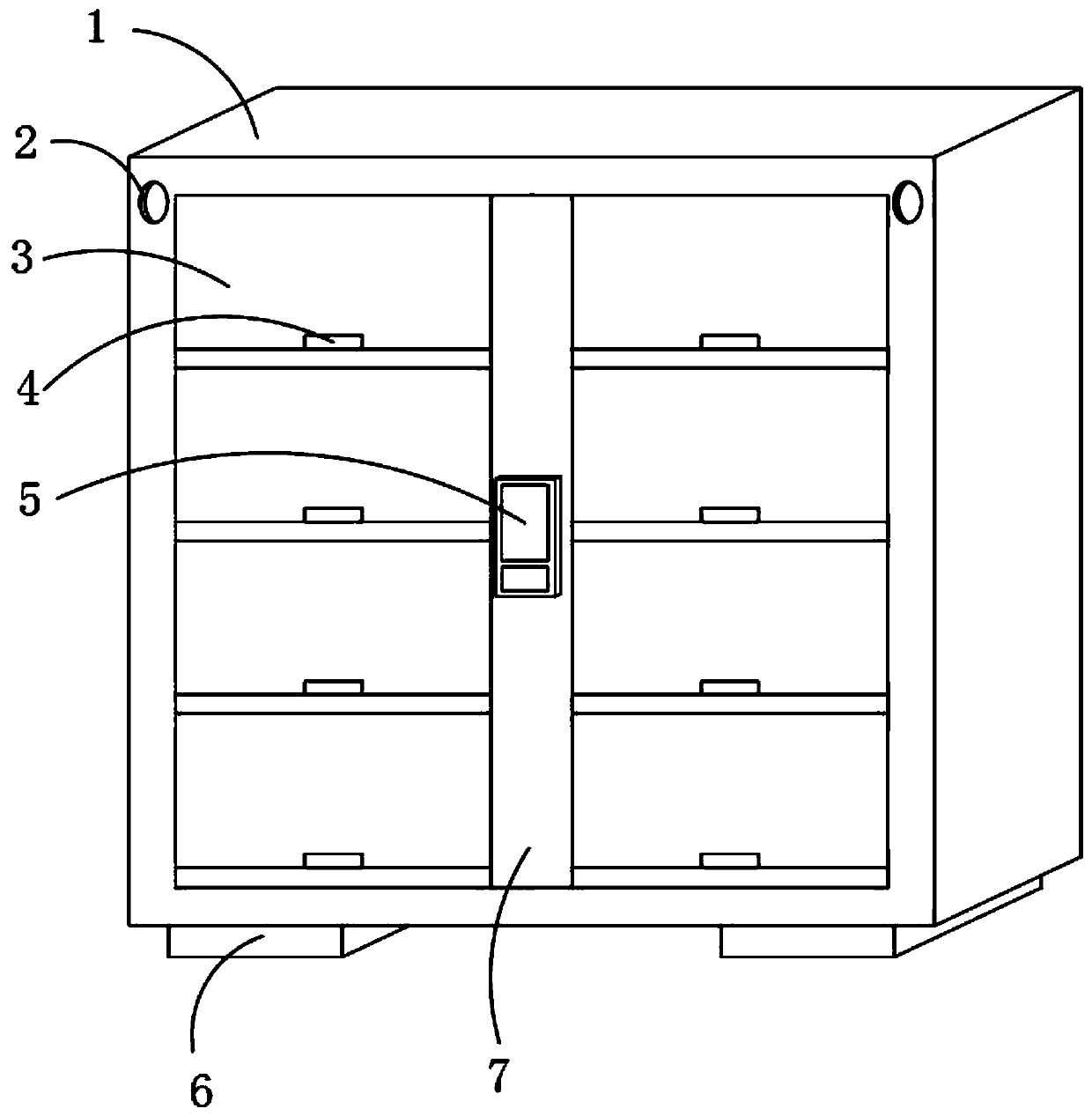
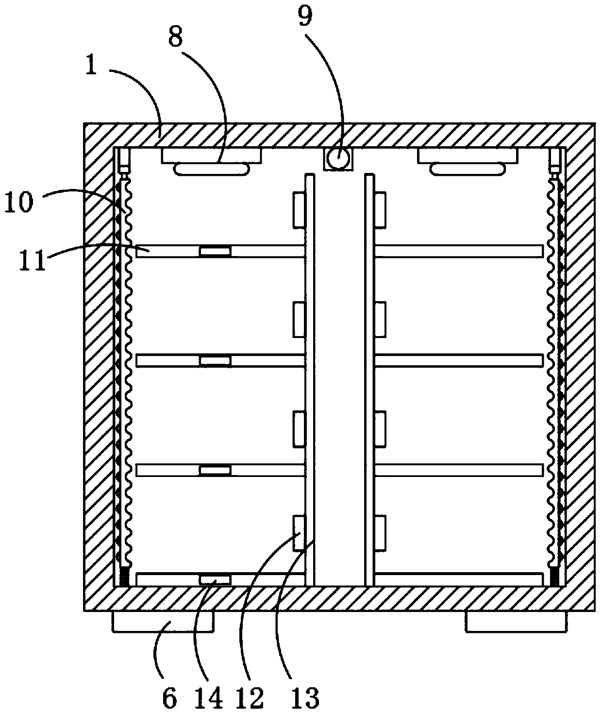
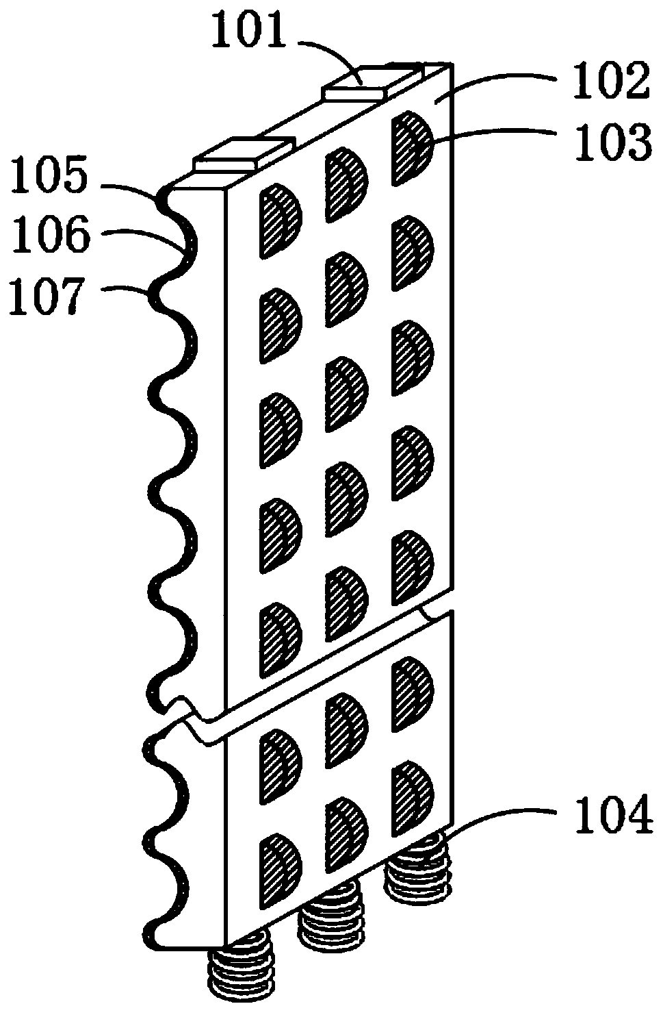
[0033] The specific embodiments of the present invention are described below with reference to the accompanying drawings. figure 1 , figure 2 , image 3 as well as Figure 4 ,in, figure 1 It is a schematic structural diagram of an intelligent wardrobe of the present invention; figure 2 It is a schematic diagram of the internal body structure of an intelligent wardrobe of the present invention; image 3 It is a schematic structural diagram of the sterilization mechanism of the present invention; Figure 4 A flow chart A of an intelligent wardrobe and a control method thereof of the present invention; Figure 5 A flow chart B of an intelligent wardrobe and a control method thereof of the present invention; in the specific implementation process, such as Figure 1-2 As shown in the figure, a smart wardrobe and a control method for the smart wardrobe include a cabinet body 1, and two stop bars 13 in a vertical direction are symmetrically arranged at the inner middle position of the cabinet body 1, and the outer sides of the two stop bars 13 are equally spaced. A plurality of storage boards 11 are provided, and a storage room is formed between each of the storage boards 11 and the gear lever 13 , and a cabinet door 3 is movably connected to the outside of the multiple storage rooms. A baffle 7 is provided, a display 5 is arranged on the baffle 7, an intelligent door lock 4 is arranged between the cabinet door 3 and the storage board 11, a base 6 is arranged on both sides of the bottom of the cabinet 1, and the display 5 is communicatively connected with a server terminal, smoke alarms 2 are arranged on both sides of the top of the cabinet 1;
[0034] The inner top of the cabinet 1 is provided with a temperature and humidity sensor 9 and two ultraviolet lamps 8, the two ultraviolet lamps 8 are located on both sides of the temperature and humidity sensor 9, and a sterilization mechanism 10 is provided on both sides of the temperature and humidity sensor 9. The inside of the board 11 is provided with a dryer 14 , and the interior of each storage compartment and on one side of the gear lever 13 is provided with an intelligent sensor light 12 .
[0035] In the specific implementation process, such as image 3 As shown, the sterilization mechanism 10 includes a micro-vibrator 101, a side reflector 102, a rubber bump 103, a damping spring 104, a convex portion 105, a concave portion 106 and a coating 107, and the side reflector 102 is located in the cabinet respectively. Two groups of micro-vibrators 101 are arranged on the top of the side reflector 102 on both sides of the interior of the body 1, and the top of the micro-vibrators 101 are fixed on the top of the cabinet 1, and the bottom of the side reflector 102 is connected to the Bottom of cabinet 1;
[0036]One side of the side reflector 102 is provided with a plurality of rubber bumps 103 in a rectangular array, and the other side of the side reflector 102 is provided with a plurality of protrusions 105 and a plurality of concave parts 106, and the plurality of protrusions 105 The other side of the side reflector 102 , that is, the side located at the convex portion 105 and the concave portion 106 is coated with a coating layer 107 .
[0037] In the specific implementation process, such as image 3 As shown, the sterilization mechanism 10 includes a micro-vibrator 101, a side reflector 102, a rubber bump 103, a damping spring 104, a convex portion 105, a concave portion 106 and a coating 107, and the side reflector 102 is located in the cabinet respectively. Two groups of micro-vibrators 101 are arranged on the top of the side reflector 102 on both sides of the interior of the body 1, and the top of the micro-vibrators 101 are fixed on the top of the cabinet 1, and the bottom of the side reflector 102 is connected to the Bottom of cabinet 1;
[0038] One side of the side reflector 102 is provided with a plurality of rubber bumps 103 in a rectangular array, and the other side of the side reflector 102 is provided with a plurality of protrusions 105 and a plurality of concave parts 106, and the plurality of protrusions 105 The other side of the side reflector 102, that is, the side located at the convex portion 105 and the concave portion 106, is coated with a coating 107; the coating 107 adopts a silver coating with high reflection intensity .
[0039] In the specific implementation process, such as Figure 1-3 As shown, the display 5 is electrically connected to the dryer 14, the smoke alarm 2, the smart door lock 4 and the temperature and humidity sensor 9; the model of the temperature and humidity sensor 9 is SCTHWA43SDS temperature and humidity sensor, and the model of the smoke alarm 2 is HZJB-1 Home smoke alarms.
[0040] In the specific implementation process, such as Figure 1-3 As shown, the server terminal may be one or more of a PC, a mobile phone, and a home cloud.
[0041] In the specific implementation process, such as Figure 4 As shown in the figure, a smart wardrobe and a control method for the smart wardrobe are characterized in that the specific steps are:
[0042] S1: First, the display 5 collects and processes the face signal of the character and the clothes signal inside the wardrobe, and compares, recognizes and analyzes the signal with the database in the display 5;
[0043] S2: After the analysis of the display 5 is completed, the command signal is issued to the smart door lock 4, and the smart door lock 4 is automatically opened at this time;
[0044] S3: After the intelligent door lock 4 is automatically opened, and a corresponding command is issued to the lighting system, the intelligent sensor light 12 in the lighting system is turned on;
[0045] S4: The user places the play clothes, closes the door, and both the smart door lock 4 and the lighting system are turned off.
[0046] 8 . The smart wardrobe and the control method for the smart wardrobe according to claim 7 , wherein the display 5 needs to input and store the user's face before use to form a database. 9 .
[0047] In the specific implementation process, such as Figure 4 As shown, before the display 5 is used, the user's face needs to be input and stored to form a database.
[0048] In the specific implementation process, such as Figure 5 As shown, the specific steps for the display 5 to collect and process the clothes signal are:
[0049] S11: The display 5 acquires clothes signals inside the wardrobe, including temperature and humidity signals, clothes storage signals and smoke signals;
[0050] S12: Send the acquired signal to the server terminal, and the server terminal will compare and analyze the received signal with the database;
[0051] S13: After the analysis of the server is completed, an order is issued to the dryer 14, the ultraviolet lamp 8 and the smoke alarm 2, so as to perform drying, sterilization and smoke alarm processing on the wardrobe.
[0052] In the specific implementation process, such as Figure 5 As shown, before the server terminal is used, it is necessary to input and store the temperature and humidity value range and smoke range value of the wardrobe to form a database.
[0053] The working principle of the present invention is as follows: when using, the user first inputs the face signal to the display 5, and stores the face signal through the display 5, thereby forming a face database, and when in use, the user can recognize the face through the face recognition. The display 5 is controlled by the display 5, and the intelligent door lock 4 is controlled by the display 5, the corresponding intelligent door lock 4 can be opened, and the clothes are placed on the storage board 11 inside the cabinet 1;
[0054] In the process of use, the display 5 collects and processes the face signal of the person and the clothes signal inside the wardrobe, and compares, recognizes and analyzes the signal with the database in the display 5; after the analysis of the display 5 is completed, the command signal is issued When the smart door lock 4 is reached, the smart door lock 4 is automatically turned on; after the smart door lock 4 is automatically turned on, a corresponding command is issued to the lighting system, and the smart sensor light 12 in the lighting system is turned on; The door lock 4 and the lighting system are both turned off;
[0055] During use, the display 5 acquires clothes signals inside the wardrobe, including temperature and humidity signals, clothes storage signals and smoke signals; sends the acquired signals to the server terminal, and the server terminal compares and analyzes the received signals with the database; After the analysis of the server is completed, the dryer 14, the ultraviolet lamp 8 and the smoke alarm 2 are given orders to dry, sterilize the wardrobe and process the smoke alarm;
[0056] When the inside of the cabinet 1 needs to be sterilized, the ultraviolet lamp 8 is controlled to irradiate first, and the micro vibrator 11 is controlled to drive the side reflector 102 to vibrate. When the side reflector 102 vibrates, the ultraviolet lamp can be made to vibrate. 8. The ultraviolet rays irradiated on the side reflector 102 exhibit multi-angle irregular reflection angles, and are reflected into each storage room, so that the clothes in each storage room can be sterilized. Both the block 103 and the spring 104 play a certain role in shock absorption, and the vibration intensity of the mode side reflector 102 is too large, which affects the stability of the cabinet 1 .
[0057] Compared with the related art, a smart wardrobe and a control method for the smart wardrobe provided by the present invention have the following beneficial effects:
[0058] The invention provides a smart wardrobe and a control method for the smart wardrobe. By setting a smart door lock and a face recognition system, the face recognition system can be connected to a server terminal through communication, and a user can remotely check the temperature and humidity inside the wardrobe through the server terminal. Observing the storage situation of clothes and smoke, and issuing corresponding instructions to adjust the internal situation, the degree of intelligence is higher, and there is no need for staff to observe the scene in person, saving time and effort, and setting up a face recognition system and smart door locks The cooperation of the wardrobe ensures higher safety performance and stronger stability of the wardrobe. Secondly, the interior of the wardrobe is provided with the ultraviolet lamp 8 and the sterilization mechanism 10. The interior of the sterilization mechanism 10 is provided with a side reflector 102. Due to the side reflection The plate 102 is coated with a silver coating, then the light generated by the ultraviolet lamp 8 can reflect the light into multiple storage rooms through the side reflector 102, so as to ensure that the clothes in the storage room can be sterilized. Finally, the present invention By arranging rubber bumps 103 on one side of the side reflector 102 to press against the inside of the cabinet 1 , and setting the other side into an uneven shape, and at the same time arranging the micro-vibrator 101 on the top of the side reflector 102 , the side reflector 102 To vibrate, a shock-absorbing spring 104 is arranged at the bottom to connect to the inner bottom of the cabinet 1, so when the light hits the uneven side of the side reflector 102, the micro-vibrator 101 drives the side reflector 102 to vibrate, which can make the reflected The light is reflected from multiple angles, thus ensuring that each storage room can receive ultraviolet light, which is more flexible and practical.
[0059] The foregoing has shown and described the basic principles, main features and advantages of the present invention. Those skilled in the art should understand that the present invention is not limited by the above-mentioned embodiments, and the above-mentioned embodiments and descriptions are only preferred examples of the present invention, and are not intended to limit the present invention, without departing from the spirit and scope of the present invention. Under the premise, the present invention will also have various changes and improvements, and these changes and improvements all fall within the scope of the claimed invention. The claimed scope of the present invention is defined by the appended claims and their equivalents.

PUM

no PUM

Description & Claims & Application Information

We can also present the details of the Description, Claims and Application information to help users get a comprehensive understanding of the technical details of the patent, such as background art, summary of invention, brief description of drawings, description of embodiments, and other original content. On the other hand, users can also determine the specific scope of protection of the technology through the list of claims; as well as understand the changes in the life cycle of the technology with the presentation of the patent timeline. Login to view more.

Similar technology patents

Classification and recommendation of technical efficacy words

  • High degree of intelligence
  • Improve security performance

Security protection cover for numerical control cutting machine

InactiveCN102699755AImprove security performanceReduce the spread of noiseMaintainance and safety accessoriesEngineeringNumerical control
Owner:苏州赛特尔集团机械有限公司
Why Eureka
Try Eureka