
Computed tomography device

A tomography, computer technology, applied in the directions of computed tomography, echo tomography, radiation generation arrangement, etc., can solve the problems of poor flexibility, inability to meet the needs of use, inconvenient adjustment of scanning equipment, etc., to achieve convenient and flexible use. Effect

Inactive Publication Date: 2020-08-25
WEIFANG UNIV OF SCI & TECH
View PDF0 Cites 0 Cited by
  • Summary
  • Abstract
  • Description
  • Claims
  • Application Information

AI Technical Summary

Problems solved by technology

[0004] The purpose of the present invention is to solve the shortcomings of single detector scanner in the existing computer tomography equipment, the scanning equipment is inconvenient to adjust, the flexibility is poor, and it cannot meet the needs of use, and a computer tomography device is proposed

Method used


Image

  • Computed tomography device
  • Computed tomography device
  • Computed tomography device

Examples


Embodiment 1

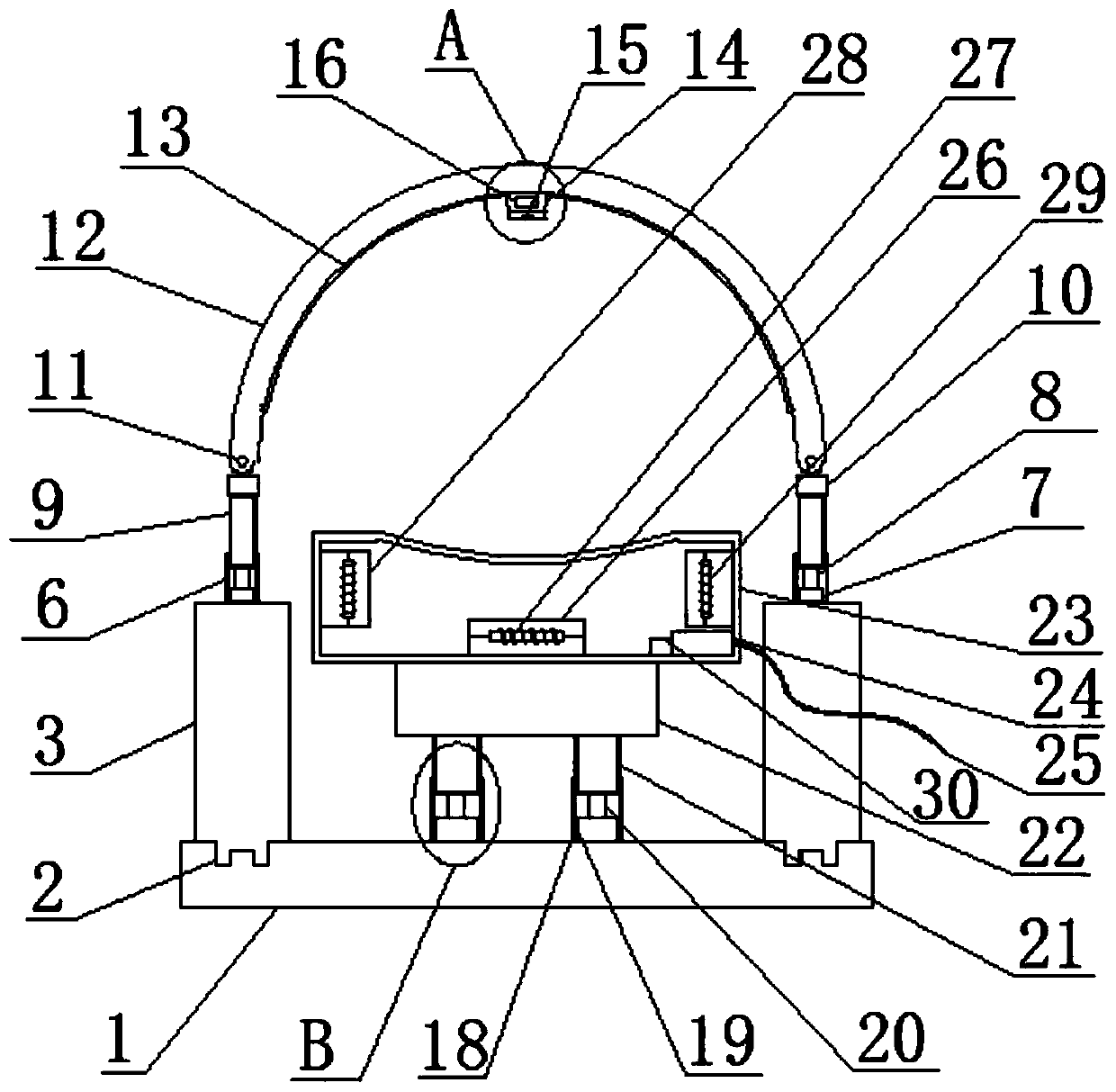
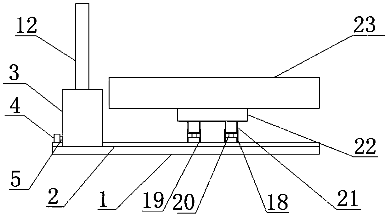
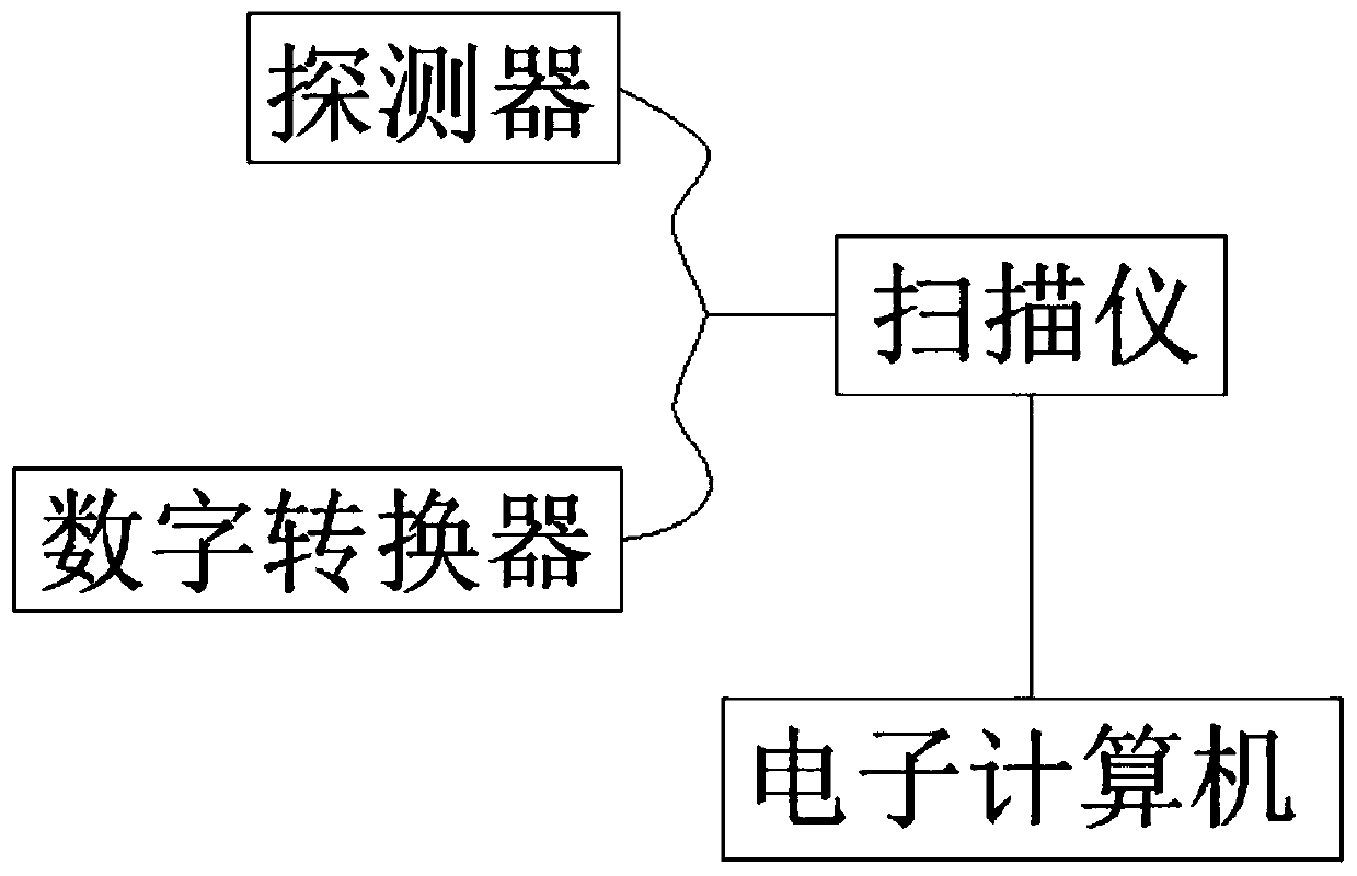
[0025] refer to Figure 1-5 , a computed tomography device, comprising a base 1, two first chutes 2 are provided on the top surface of the base 1, and support columns 3 are slidably connected in the two first chutes 2, and one side of the top surface of the base 1 Two first motors 4 are fixedly arranged, and the output shafts of the two first motors 4 are fixedly connected with one end of the first telescopic rod 5, and the other ends of the two first telescopic rods 5 are respectively fixedly connected with the two supporting columns 3 The top surfaces of the two support columns 3 are fixedly connected with the first cylindrical body 6, and the second motor 7 is fixedly arranged in the two first cylindrical bodies 6, and the output shafts of the two second motors 7 are fixed. The second telescopic rod 8 is connected, and the tops of the two second telescopic rods 8 are fixedly connected with the first sliding rod 9, and the two first sliding rods 9 are respectively slidably c...

Embodiment 2

[0034] refer to Figure 1-5 , a computed tomography device, comprising a base 1, two first chutes 2 are provided on the top surface of the base 1, and support columns 3 are slidably connected in the two first chutes 2, and one side of the top surface of the base 1 Two first motors 4 are fixed by screws, and the output shafts of the two first motors 4 are fixedly welded with one end of the first telescopic rod 5, and the other ends of the two first telescopic rods 5 are respectively fixedly welded on two supports. On one side of the column 3, the top surfaces of the two support columns 3 are fixedly welded with a first cylinder 6, and the two first cylinders 6 are fixed with a second motor 7 by screws, and the two second motors 7 The output shafts are fixedly welded with the second telescopic rod 8, and the tops of the two second telescopic rods 8 are fixedly welded with the first sliding rod 9, and the two first sliding rods 9 are respectively slidably connected to the inner w...


PUM


Abstract

The invention belongs to the technical field of tomography, and particularly relates to a computed tomography device. For the problems that according to single-detector scanning instruments in existing computed tomography equipment, the scanning equipment is inconvenient to adjust, the flexibility is poor, and the use requirements cannot be met, the following scheme is proposed: the computed tomography device comprises a base, wherein two first sliding grooves are formed in the top surface of the base, supporting columns are slidingly connected with the interiors of both the first sliding grooves, two first motors are fixedly arranged on one side of the top surface of the base, and an output shaft of each first motor in the two first motors is fixedly connected with one end of a corresponding first telescoping rod. According to the computed tomography device, by pushing the supporting columns to horizontally move in the first sliding grooves through the first motors, the whole body ofa patient can be scanned, by pushing first sliding rods to slide in first barrels through second motors, the height of a scanning frame can be adjusted, and a scanning instrument can conduct scanningchecking on the patient at multiple angles when sliding on the scanning frame, so that use is convenient and flexible.

Description

technical field [0001] The invention relates to the technical field of tomography, in particular to a computer tomography device. Background technique [0002] Computerized tomography, or CT (Computed Tomography), uses precisely collimated X-ray beams, γ-rays, ultrasound, etc., together with highly sensitive detectors, to conduct cross-sectional scans one by one around a certain part of the human body. It has the characteristics of fast scanning time and clear images, and can be used for the examination of various diseases. [0003] The single-detector scanner in the existing computed tomography equipment is inconvenient to adjust the scanning equipment, has poor flexibility, and cannot meet the use requirements. Contents of the invention [0004] The purpose of the present invention is to solve the disadvantages of single-detector scanner in the existing computer tomography equipment, the scanning equipment is inconvenient to adjust, the flexibility is poor, and it canno...

Claims


Application Information

Patent Timeline
Patent Type & Authority Applications(China)
IPC IPC(8): A61B6/03
CPCA61B6/035A61B6/40
Inventor 张翠萍
Owner WEIFANG UNIV OF SCI & TECH
Learn More