
Auxiliary grinding system

A technology of auxiliary system and grinding device, applied in the direction of grinding machine parts, grinding/polishing equipment, metal processing equipment, etc., can solve the problems of long training time, less operation than experienced users, and a lot of time to search. , to achieve the effect of improving work efficiency

Inactive Publication Date: 2020-08-25
FALCON MACHINE TOOLS
View PDF4 Cites 3 Cited by
  • Summary
  • Abstract
  • Description
  • Claims
  • Application Information

AI Technical Summary

Problems solved by technology

[0004] According to the above, it can be known that in the use of common grinding wheel grinders, factors such as the processed object and the processing method must be considered to select and allocate the corresponding grinding wheel for processing and manufacturing. However, it often takes a lot of time and energy to process the grinding wheel and the workpiece. Especially when newcomers come to use this kind of machinery, the operation is not as good as those with experience in use, and when replacing the grinding wheel, it is often necessary to find the corresponding size and material in the grinding wheel inventory, even if there is experience in use It may not be able to find and install quickly, relatively new recruits need to spend a lot of time to find, and the new recruits not only take a long time to train, they cannot be put into work immediately, and the wear of the grinding wheel after processing must be further adjusted The amount of knife feed needs to be adjusted manually, which is not in line with economic benefits. Therefore, there is still a lot of room for improvement for the development of the industry that is constantly seeking innovation and change.

Method used


Image

  • Auxiliary grinding system
  • Auxiliary grinding system
  • Auxiliary grinding system

Examples


Embodiment Construction

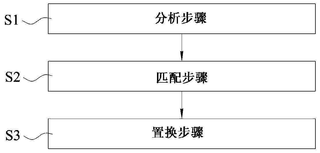
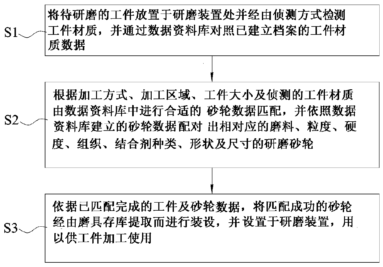
[0014] see Figure 1 to Figure 2 Shown, be grinding auxiliary system of the present invention, its system comprises the following steps:

[0015] Step S1: analysis step: place the workpiece to be ground on the grinding device and detect the material of the workpiece through the detection method, and compare the material data of the workpiece with the established file through the data database;

[0016] Step S2: Matching step: according to the speed, precision and roughness set by the user, fine-tune the processing parameters and match the detected workpiece material to match the appropriate grinding wheel data from the data database, and according to the grinding wheel data established in the data database Matching grinding wheels with corresponding abrasives, particle size, hardness, structure, binder type, shape and size for users to choose; and

[0017] Step S3: Replacement step: according to the matched workpiece and grinding wheel data, the matched grinding wheel is extr...


PUM


Abstract

The invention relates to an auxiliary grinding system for use before and after a grinding operation. The system comprises the steps of S1 an analysis step of placing a to-be-ground workpiece at a grinding device, detecting the material of the workpiece in a detection mode, and comparing the material data of the workpiece with an established file through a data database; S2 a matching step of finely adjusting processing parameters according to the speed, precision and roughness set by a user, matching the processing parameters with the detected material of the workpiece to perform grinding wheel data matching, and matching a corresponding grinding wheel according to the grinding wheel data for the user to select; and S3 a substitution step of extracting the grinding wheel which is successfully matched and selected through a grinding tool storage library according to the matched workpiece and the selected grinding wheel data for installation, and arranging the grinding wheel on the grinding device for the workpiece processing, so that the material of the workpiece is detected, the grinding wheel which is suitable for processing is matched through the data database and automatically installed, and further, the procedures of selecting the grinding wheel through manual judgment and manually installing are replaced, and the working efficiency is improved.

Description

technical field [0001] The present invention is related to a grinding system, especially a method of detecting workpiece material, matching grinding wheels suitable for processing through a data database, and automatically installing them, thereby replacing manual selection of grinding wheels and manual installation procedures to improve work efficiency. Background technique [0002] Machine tools are used to manufacture various machines and processing equipment. According to their functions, machine tools can be divided into two categories: metal cutting machine tools and metal forming machine tools. The former includes lathes, drilling machines, milling machines, grinding machines, planers, etc.; Those include punches, shears, etc. Machine tools are composed of a number of components, including drilling machines, milling machines, grinders, planers and other machine tools that use rotary cutting motions. Among them, machine tools with computer numerical control functions c...

Claims


Application Information

Patent Timeline
IPC IPC(8): B24B49/00
CPCB24B49/00
Inventor 张宝铭吴正家
Owner FALCON MACHINE TOOLS
Learn More