Vehicle and vehicle control method
A control method and vehicle technology, applied in the field of vehicle and vehicle control, can solve the problems that exhaust gas cannot be effectively used, vehicles cannot provide high-quality air for traction motor cooling, etc., so as to reduce the probability of blockage, realize energy saving and consumption reduction, The effect of reducing the occupied space
Active Publication Date: 2020-08-25
CRRC QINGDAO SIFANG CO LTD
7 Cites 0 Cited by
AI-Extracted Technical Summary
Problems solved by technology
[0005] The main purpose of the present invention is to provide a vehicle and a vehicle control method to solve the problems in the prior art that the exhaust ...
Method used
As shown in Figure 2, traction motor mechanism 20 comprises two traction motors, and two traction motors comprise first traction motor 21 and second traction motor 22; Air duct assembly 33 also comprises: main air duct 331, main wind One end of the road 331 is connected with the discharge fan 34; the first air passage 332, one end of the first air passage 332 is connected with the main air passage 331 away from the end of the discharge fan 34; the second air passage 333, one end of the second air passage 333 is connected with The main air duct 331 is connected to one end away from the discharge fan 34; wherein, the air outlet assembly 32 includes a first air outlet 321 and a second air outlet 322, and the first air outlet 321 is located at the end of the first air duct 332 away from the main air duct 331, The first air outlet 321 communicates with the first traction motor 21 ; the second air outlet 322 is located at the end of the second air duct 333 away from the main air duct 331 , and the second air outlet 322 communicates with the second traction motor 22 . That is to say, the number of air ducts can be adjusted reasonably according to the change in the number of traction motors, so that each air duct can correspond to a traction motor independently, thereby ensuring the cooling effect. Of course, the number of traction motors is not limited to two, mainly because two traction motors are generally provided on existing vehicles.
As shown in Figures 2 and 3, the main air duct 331 is provided with an air outlet 334; the exhaust gas discharge device 30 also includes: a regulating plate 39, which is arranged in the main air duct 331 and is movable relative to the main air duct 331 Arranged accordingly, the adjustment plate 39 has a first position where the air outlet 334 is closed and the main air duct 331 is opened, and a second position where the main air duct 331 is closed and the air outlet 334 is opened, and the adjustment plate 39 is in the first position and the second position are switchably set. When the traction motor is normally cooled, the adjusting plate 39 closes the exhaust outlet 334 on the main air duct 331, and the waste gas in the main air duct 331 passes through the first air duct 332 and the second air duct 333 under the action of the discharge fan 34. Blow to both traction motors separately. When the traction motor does not need to be cooled, the adjusting plate 39 rotates and cuts off the ventilation path of the main air duct 331, and the sucked exhaust gas is directly discharged through the air outlet 334 on the main air duct 331, and no longer passes through the first air duct 332, The second air duct 333 . By setting the adjusting plate 39, the cooling of the traction motor can be adjusted, and it is possible to control whether the traction motor needs to be cooled according to the requirement.
In the present embodiment, exhaust gas discharge device 30 comprises air duct assembly 33 and exhaust fan 34, and air outlet assembly 32 is arranged on air duct assembl...
Abstract
The invention provides a vehicle and a control method of the vehicle. The vehicle includes a vehicle body with a passenger room, a traction motor mechanism arranged on the vehicle body, and a waste gas exhaust device arranged on the vehicle body, wherein the traction motor mechanism comprises a traction motor, a temperature sensor is arranged on the traction motor, and the temperature sensor is used for detecting the real-time temperature of the traction motor; and the waste gas exhaust device is provided with an air inlet and an air outlet assembly, the air inlet is communicated with the passenger room, and the air outlet assembly is communicated with the traction motor, so that waste gas in the passenger room is conveyed to the traction motor by the waste gas exhaust device to cool the traction motor. The vehicle solves the problem that in the prior art, waste gas in a passenger room of a vehicle cannot be effectively utilized, and the vehicle cannot provide high-quality air for traction motor cooling.
Application Domain
Railway heating/coolingCooling/ventillation arrangement +1
Technology Topic
Electric machineryTraction motor +5
Image
Examples
- Experimental program(1)
Example Embodiment
[0028] It should be noted that the embodiments in this application and the features in the embodiments can be combined with each other if there is no conflict. Hereinafter, the present invention will be described in detail with reference to the drawings and in conjunction with the embodiments.
[0029] It should be pointed out that the following detailed descriptions are all illustrative and are intended to provide further explanations for the application. Unless otherwise indicated, all technical and scientific terms used herein have the same meaning as commonly understood by those of ordinary skill in the technical field to which this application belongs.
[0030] It should be noted that the terms used here are only for describing specific implementations, and are not intended to limit the exemplary implementations according to the present application. As used herein, unless the context clearly indicates otherwise, the singular form is also intended to include the plural form. In addition, it should also be understood that when the terms "comprising" and/or "including" are used in this specification, they indicate There are features, steps, operations, devices, components, and/or combinations thereof.
[0031] In order to solve the problems that the exhaust gas in the passenger compartment of the vehicle in the prior art cannot be effectively used and the vehicle cannot provide high-quality wind for cooling the traction motor, the present invention provides a vehicle and a vehicle control method.
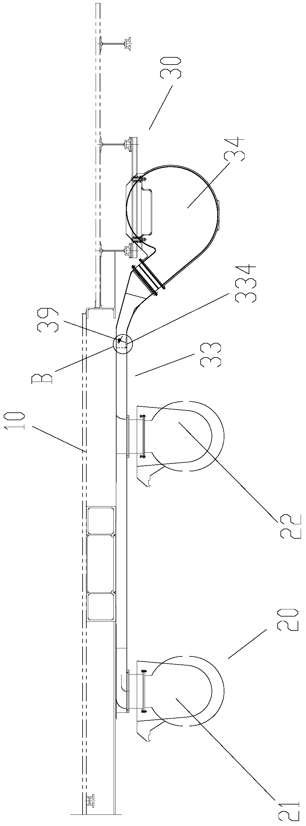
[0032] Please refer to Figure 1 to Figure 4 The vehicle of the present invention includes a vehicle body 10, a traction motor mechanism 20, and an exhaust emission device 30. The car body 10 has a passenger compartment; the traction motor mechanism 20 is arranged on the car body 10, the traction motor mechanism 20 includes a traction motor, and a temperature sensor is arranged on the traction motor. The temperature sensor is used to detect the real-time temperature of the traction motor; On the vehicle body 10, the exhaust gas discharge device 30 has an air inlet 31 and an air outlet assembly 32. The air inlet 31 communicates with the passenger compartment, and the air outlet assembly 32 communicates with the traction motor, so that the exhaust gas discharge device 30 conveys the exhaust gas in the passenger compartment to Traction motor to cool the traction motor.
[0033] The vehicle of the present invention includes a vehicle body 10, a traction motor mechanism 20, and an exhaust gas emission device 30. The exhaust gas emission device 30 is used to transport exhaust gas in the passenger compartment to the traction motor of the traction motor mechanism 20 to achieve cooling of the traction motor, which is effective The exhaust gas discharged from the vehicle is used to cool the traction motor to achieve energy saving and consumption reduction; and the exhaust gas in the passenger compartment is cleaner than the outside air, which greatly reduces the probability of the exhaust gas discharge device 30 being blocked. At the same time, because there is no need to configure an additional exhaust fan, the space occupied by the equipment under the vehicle and the maintenance thereof are reduced.
[0034] In this embodiment, the traction motor mechanism 20 is provided on the outside of the vehicle body 10 and at the bottom of the vehicle body 10.
[0035] In this embodiment, the exhaust gas discharge device 30 includes an air duct assembly 33 and an exhaust fan 34. The air outlet assembly 32 is arranged on the air duct assembly 33; the exhaust fan 34 is arranged on the vehicle body 10, and the exhaust fan 34 is connected to the passenger compartment. The exhaust fan 34 is in communication with the air duct assembly 33 so that the exhaust fan 34 transports the exhaust gas in the passenger compartment to the air duct assembly 33 and discharges it through the air outlet assembly 32. This arrangement enables the exhaust fan to combine the functions of a cooling fan and an exhaust gas exhaust fan, which can achieve exhaust gas emission and cooling of the traction motor, reduce equipment occupation space, and reduce production costs.
[0036] Preferably, the discharge fan 34 is a frequency conversion fan.
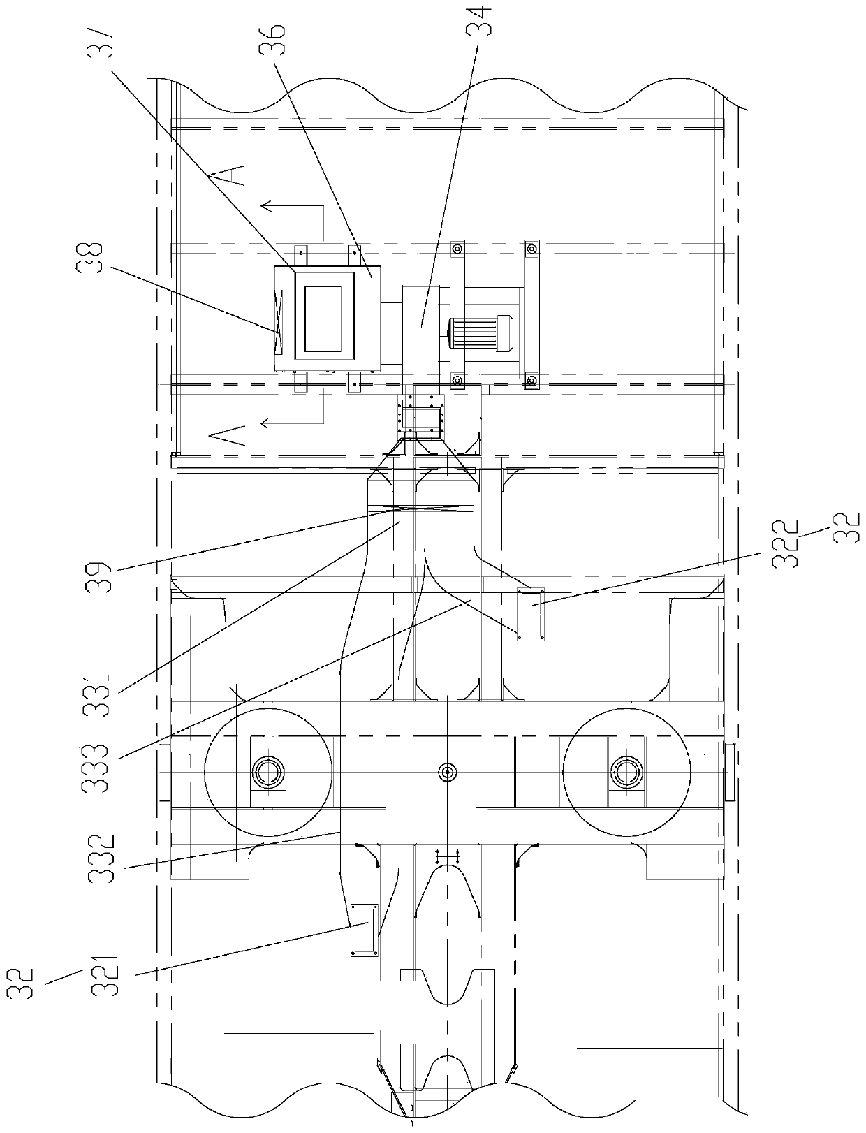
[0037] Such as figure 2 As shown, the traction motor mechanism 20 includes two traction motors, the two traction motors include a first traction motor 21 and a second traction motor 22; the air duct assembly 33 also includes: a main air duct 331, one end of the main air duct 331 and the exhaust The fan 34 is connected; the first air duct 332, one end of the first air duct 332 is connected to the end of the main air duct 331 away from the discharge fan 34; the second air duct 333, one end of the second air duct 333 is away from the main air duct 331 for discharge One end of the fan 34 is connected; wherein the air outlet assembly 32 includes a first air outlet 321 and a second air outlet 322, the first air outlet 321 is located at the end of the first air duct 332 away from the main air duct 331, and the first air outlet 321 is connected to The first traction motor 21 is in communication; the second air outlet 322 is located at an end of the second air duct 333 away from the main air duct 331, and the second air outlet 322 is in communication with the second traction motor 22. That is to say, the number of air ducts can be adjusted reasonably according to the change of the number of traction motors, so that each air duct can individually correspond to a traction motor, thereby ensuring the cooling effect. Of course, the number of traction motors is not limited to two, mainly in existing vehicles, two traction motors are generally provided.
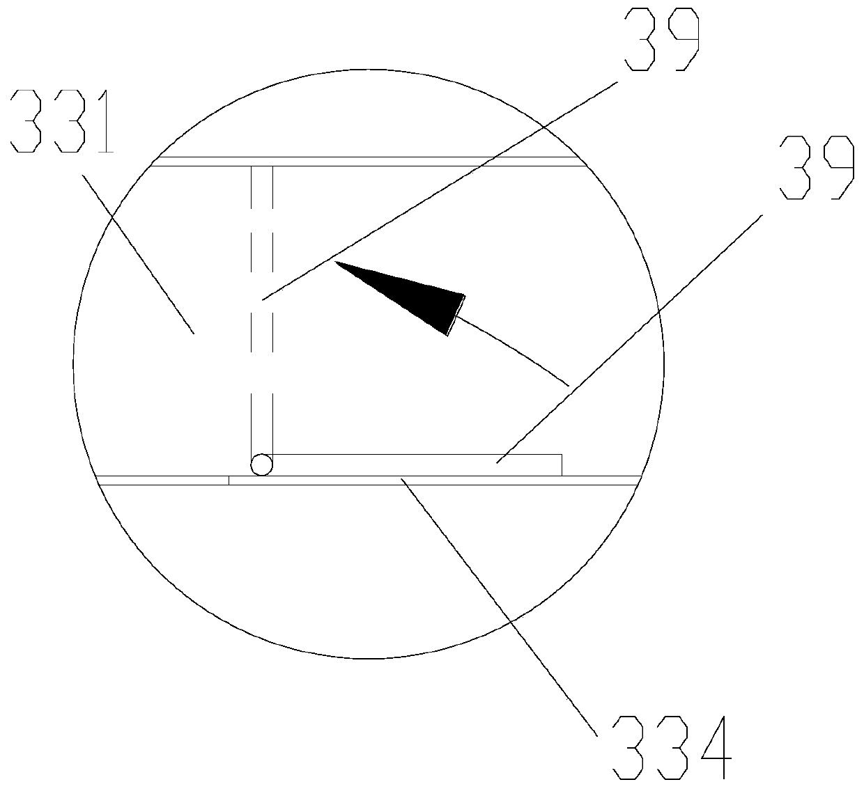
[0038] Such as figure 2 with image 3 As shown, the main air duct 331 is provided with an exhaust port 334; the exhaust gas discharge device 30 also includes: an adjusting plate 39 arranged in the main air duct 331 and movably arranged relative to the main air duct 331, the adjusting plate 39 has a The first position where the air outlet 334 is closed and the main air duct 331 is opened and the second position where the main air duct 331 is closed and the air outlet 334 is opened, the adjustment plate 39 is switchable between the first position and the second position Set up. When the traction motor is normally cooled, the adjusting plate 39 closes the air outlet 334 on the main air duct 331. At this time, the exhaust gas in the main air duct 331 passes through the first air duct 332 and the second air duct 333 under the action of the exhaust fan 34. Blow to the two traction motors respectively. When the traction motor does not need to be cooled, the adjustment plate 39 rotates and cuts off the ventilation path of the main air duct 331, and the inhaled exhaust gas is directly discharged through the exhaust port 334 on the main air duct 331, and no longer passes through the first air duct 332, The second wind channel 333. By setting the adjusting plate 39, the cooling of the traction motor can be adjusted, and whether the traction motor needs cooling can be controlled according to demand.
[0039] Specifically, the regulating plate 39 is an electric valve plate.
[0040] Specifically, the main air duct 331 has a first end and a second end opposite to each other, the first end of the main air duct 331 is provided with a main air duct air inlet, and the second end of the main air duct 331 is provided with a main air duct outlet The air inlet of the main air duct is connected with the exhaust fan 34, and the air outlet of the main air duct is connected with the first air duct 332 and the second air duct 333; the air outlet 334 is arranged on the side wall of the main air duct 331 and is located in the main air duct Between the air inlet and the air outlet of the main air duct. It should be noted that the air outlet 334 is not used to connect the main air duct 331 with the first air duct 332 and the second air duct 333, but is provided on the main air duct 331 for connecting the main air duct 331 An "exhaust port" through which the exhaust gas in the air duct 331 is directly discharged outward. In other words, the air outlet 334 is not the air outlet of the main air duct.
[0041] Such as figure 2 with Figure 4 As shown, the exhaust gas discharge device 30 further includes a connecting air duct 35 and a wind box 36. One end of the connecting air duct 35 is connected to the car body 10; the end of the connecting air duct 35 away from the car body 10 is connected to the wind box 36, and the passenger compartment is connected to the wind box 36 through the connecting air duct 35; the exhaust fan 34 is connected to the wind box 36 to enable passengers The indoor exhaust gas passes through the connecting air duct 35 and the wind box 36 in sequence under the action of the exhaust fan 34 and then enters the air duct assembly 33. Wherein, the discharge fan 34 is arranged on one side of the wind box 36 and connected to the side wall of the wind box 36. In this way, the arrangement of the connecting air duct 35 facilitates the connection of the exhaust fan 34 and the vehicle body 10. The arrangement of the bellows 36 can connect the exhaust fan 34 to the side wall of the bellows 36 to prevent the overall height of the equipment under the vehicle from being too high; and the arrangement of the bellows 36 facilitates the installation of the first control valve 37 and the second control valve 38.
[0042] Such as Figure 4 As shown, the wind box 36 has a first wind box air inlet 361, and the connecting air duct 35 is connected to the wind box 36 through the first wind box air inlet 361; the first wind box air inlet 361 is provided with a first control valve 37 to control the first wind box The air inlet 361 is opened or closed. When the exhaust gas needs to be discharged, the first control valve 37 is opened, and the first control valve 37 is closed when the vehicle enters or exits the tunnel or crosses vehicles to prevent pressure fluctuations from being introduced into the vehicle body.
[0043] Specifically, the first wind box air inlet 361 is provided on the top of the wind box 36.
[0044] In this embodiment, the first control valve 37 is a pressure protection valve. The pressure protection valve has only two states: open and closed. In this way, the pressure protection valve is closed to prevent pressure fluctuations from being introduced into the vehicle body when the vehicle enters or exits the tunnel or meets. Specifically, the closing time of the pressure protection valve is usually 1 min to 10 min. If the pressure protection valve is temporarily closed, the exhaust gas from the passenger compartment will be zero.
[0045] Such as Figure 4 As shown, the wind box 36 has a second wind box air inlet 362 for sucking outside air into the wind box 36, and a second control valve 38 is provided on the second wind box air inlet 362 to control the opening and closing of the second wind box air inlet 362. Opening. When the first control valve 37 is closed, the second control valve 38 can be fully opened, and the exhaust fan 34 draws outside air to cool the traction motor. It should be noted that the temperature of the traction motor is usually very high and higher than the outside temperature. Even in summer, the temperature of the outside air is lower than the temperature of the traction motor. Therefore, it is possible to temporarily use the outside air to cool the traction motor. Especially in severe cold areas or winter, the cooling effect of this method will be improved.
[0046] Specifically, the second wind box air inlet 362 is provided on the side of the wind box 36.
[0047] In this embodiment, the second control valve 38 is an electric shutter damper. Such a setting can be used to adjust the air inlet flow rate of the air inlet 362 of the second wind box.
[0048] Specifically, the wind box 36 is suspended at the bottom of the vehicle body.
[0049] In this embodiment, the exhaust gas discharge device 30 further includes a connecting hose, one end of the connecting hose is connected to the exhaust fan 34, and the other end of the connecting hose is connected to the main air duct 331.
[0050] The vehicle of the present application uses the exhaust gas in the passenger compartment to cool the traction motor. The exhaust gas in the passenger compartment is a cooler cooling air, which has a better cooling effect on the traction motor. Therefore, the exhaust fan with a smaller volume flow can be selected when selecting the exhaust fan. Fan. In addition, the exhaust gas in the passenger compartment is a cleaner cooling air, avoiding the blocking of the exhaust fan caused by foreign air for air cooling, such as catkins and other impurities, and will not increase the air inlet resistance of the exhaust fan. At the same time, the vehicle eliminates the exhaust fan. In summary, the vehicle achieves a certain degree of energy saving.
[0051] The present invention also provides a vehicle control method, which is applied to the vehicle of the above embodiment. The vehicle control method includes: a temperature sensor detects the real-time temperature of the traction motor of the vehicle; judging the relationship between the real-time temperature and the predetermined temperature of the traction motor; judging that the real-time temperature is greater than the predetermined temperature, the vehicle exhaust emission device 30 is activated, and the vehicle The exhaust gas in the passenger compartment of the vehicle is delivered to the traction motor to cool the traction motor. Through judgment, the traction motor can be cooled when the traction motor is overheated, instead of blindly cooling at any time, so that the traction motor can be protected to a greater extent.
[0052] Specifically, the value of the temperature sensor is fed back to the network control system of the vehicle, and the network control system of the vehicle controls the opening or closing of the exhaust fan according to the relationship between the real-time temperature of the temperature sensor and the predetermined temperature.
[0053] In this embodiment, the vehicle control method further includes: after judging that the real-time temperature is greater than the predetermined temperature, judging the relationship between the flow rate of exhaust gas emissions from the passenger compartment and the flow rate of cooling air for the traction motor; judging the exhaust gas from the passenger compartment The discharge flow is equal to the flow of cooling air for the traction motor. The vehicle's regulating plate 39 is in the first position, the vehicle's second control valve 38 is closed, the vehicle's first control valve 37 is opened, and the vehicle's exhaust fan 34 is activated to pass passengers. The exhaust gas in the room cools the traction motor.
[0054] It should be noted that the flow rate of exhaust gas emission in the passenger compartment is equal to the flow rate of the air-conditioning fresh air intake in the passenger room, and the air-conditioning fresh air intake flow is usually multiple set flow values. Therefore, the flow rate of exhaust gas emissions from the passenger compartment can be determined according to the flow rate of the fresh air from the air conditioner. The cooling air flow rate of the traction motor is the predetermined cooling air flow rate required by the traction motor itself. Therefore, when the traction fan is cooled, the cooling air flow rate of the traction motor is known, and the air conditioning fresh air intake The flow rate is also known, and the relationship between the flow rate of the exhaust gas discharged from the passenger compartment and the flow rate of the cooling air of the traction motor can be judged.
[0055] In this embodiment, the vehicle control method further includes: after judging that the real-time temperature is greater than the predetermined temperature, judging the relationship between the flow rate of exhaust gas emissions from the passenger compartment and the flow rate of cooling air for the traction motor; judging the exhaust gas from the passenger compartment When the discharge flow rate is less than the flow rate of the cooling wind of the traction motor, the vehicle's regulating plate 39 is in the first position, the vehicle's second control valve 38 is opened, the vehicle's first control valve 37 is opened, and the vehicle's exhaust fan 34 is activated to pass The exhaust gas in the passenger compartment and the outside air cool the traction motor together. That is to say, when it is known that the flow rate of fresh air from the air conditioner is relatively small, it will be known that the flow rate of exhaust gas emission in the passenger compartment is less. At this time, the flow rate of exhaust gas emission in the passenger compartment is not enough to meet the cooling demand of the traction motor, and auxiliary means and The indoor exhaust gas cools the traction motor together. The external air supply can make up for the insufficient exhaust gas in the passenger compartment.
[0056] In this embodiment, the vehicle control method further includes: judging that the real-time temperature is less than or equal to the predetermined temperature, the adjusting plate 39 of the vehicle is in the second position, the second control valve 38 of the vehicle is closed, and the first control valve 37 of the vehicle is opened , The exhaust fan 34 of the vehicle is activated to directly discharge the exhaust gas in the passenger compartment to the outside. In other words, when the temperature of the traction fan is not high and does not require cooling, there is no need to use the exhaust gas in the passenger compartment to cool the traction fan. At this time, the main air duct 331 can be blocked by the adjustment plate 39, and it is necessary and at the same time to ensure that the air outlet 334 is open, the second control valve 38 is closed so that the outside air is stopped, and the first control valve 37 is opened to make the passenger compartment The exhaust gas is discharged to the outside through the wind box 36, the main air duct 331, and the exhaust port 334.
[0057] In this embodiment, the control method of the vehicle further includes: when it is detected that the vehicle needs emergency ventilation, the adjusting plate 39 of the control vehicle is in the second position, the second control valve 38 of the vehicle is closed, and the first control valve 37 of the vehicle is opened. , The exhaust fan 34 of the vehicle is activated to directly discharge the exhaust gas in the passenger compartment to the outside.
[0058] Specifically, when the vehicle needs emergency ventilation, the vehicle is in an emergency rescue state. When the vehicle's network control system detects that the grid is not supplying power to the vehicle, the vehicle cannot run at this time, the traction motor does not need to be cooled, and the vehicle only needs to maintain lighting and ventilation, etc. Just as needed.
[0059] From the above description, it can be seen that the foregoing embodiments of the present invention achieve the following technical effects:
[0060] The vehicle of the present invention includes a vehicle body 10, a traction motor mechanism 20, and an exhaust gas emission device 30. The exhaust gas emission device 30 is used to transport exhaust gas in the passenger compartment to the traction motor of the traction motor mechanism 20 to achieve cooling of the traction motor, which is effective The exhaust gas discharged from the vehicle is used to cool the traction motor to achieve energy saving and consumption reduction; and the exhaust gas in the passenger compartment is cleaner than the outside air, which greatly reduces the probability of the exhaust gas discharge device 30 being blocked. At the same time, because there is no need to configure an additional exhaust fan, the space occupied by the equipment under the vehicle and the maintenance thereof are reduced.
[0061] It should be noted that the terms "first" and "second" in the description and claims of the application and the above-mentioned drawings are used to distinguish similar objects, and not necessarily used to describe a specific sequence or sequence. It should be understood that the data used in this way can be interchanged under appropriate circumstances, so that the embodiments of the present application described herein can be implemented in a sequence other than those illustrated or described herein, for example. In addition, the terms "including" and "having" and any variations of them are intended to cover non-exclusive inclusions. For example, a process, method, system, product, or device that includes a series of steps or units is not necessarily limited to the clearly listed Those steps or units may include other steps or units that are not clearly listed or are inherent to these processes, methods, products, or equipment.
[0062] For ease of description, spatially relative terms can be used here, such as "above", "above", "above the surface", "above", etc., to describe as shown in the figure Shows the spatial positional relationship between one device or feature and other devices or features. It should be understood that the spatially relative terms are intended to encompass different orientations in use or operation other than the orientation of the device described in the figure. For example, if the device in the drawing is inverted, then a device described as "above other devices or structures" or "above other devices or structures" will be positioned as "below other devices or structures" or "on Under other devices or structures". Thus, the exemplary term "above" can include both orientations "above" and "below". The device can also be positioned in other different ways (rotated by 90 degrees or in other orientations), and the relative description of the space used here is explained accordingly.
[0063] The above are only preferred embodiments of the present invention and are not used to limit the present invention. For those skilled in the art, the present invention can have various modifications and changes. Any modification, equivalent replacement, improvement, etc., made within the spirit and principle of the present invention shall be included in the protection scope of the present invention.
PUM


Description & Claims & Application Information
We can also present the details of the Description, Claims and Application information to help users get a comprehensive understanding of the technical details of the patent, such as background art, summary of invention, brief description of drawings, description of embodiments, and other original content. On the other hand, users can also determine the specific scope of protection of the technology through the list of claims; as well as understand the changes in the life cycle of the technology with the presentation of the patent timeline. Login to view more.
Similar technology patents
Automatic box making device and method
Owner:中科天工(广东)智能技术有限公司
Machine for automatic assembly and detection of automotive connector and implementation method of machine
Owner:CHENGDU TIANCHUANG PRECISION MOLD
Anti-blocking method and equipment for biomass boiler worm feeder
InactiveCN106352368AGuarantee continuous and stable operationReduce the probability of blockage
Owner:HUNAN THERMAL POWER CONSTR CO LTD OF CHINA ENERGY ENG GRP
Multistage integrated hydrodynamic cyclone separator
Owner:BEIJING UNIVERSITY OF CIVIL ENGINEERING AND ARCHITECTURE
Garbage leachate advanced treatment method and Fenton reaction tower
Owner:深圳市百斯特环保工程有限公司
New type high-power LED driving power source
ActiveCN101621871AFacilitate intelligent dimmingRealize energy saving and consumption reduction
Owner:YANTAI AOXING ELECTRICAL EQUIP
Automatic processing production line for metal sheets
Owner:江苏扬力数控机床有限公司
Classification and recommendation of technical efficacy words
- Reduce the probability of blockage
- Realize energy saving and consumption reduction
Anti-blocking method and equipment for biomass boiler worm feeder
InactiveCN106352368AGuarantee continuous and stable operationReduce the probability of blockage
Owner:HUNAN THERMAL POWER CONSTR CO LTD OF CHINA ENERGY ENG GRP
New type high-power LED driving power source
ActiveCN101621871AFacilitate intelligent dimmingRealize energy saving and consumption reduction
Owner:YANTAI AOXING ELECTRICAL EQUIP