
A floating algae fishing device for water conservancy projects

A water conservancy project and salvage device technology, which is applied in water conservancy projects, cleaning of open water surfaces, construction, etc., can solve the problems of low salvage efficiency and the roots that cannot float algae, etc., and achieve high-efficiency salvage effects

Active Publication Date: 2022-01-25
宁夏施能达市政工程有限公司
View PDF1 Cites 0 Cited by
  • Summary
  • Abstract
  • Description
  • Claims
  • Application Information

AI Technical Summary

Problems solved by technology

The device for cleaning floating algae plants in water conservancy engineering rivers in the above-mentioned patents has the following disadvantages: the root of the floating algae cannot be pulled up well when used, and the fishing efficiency is low.

Method used


Image

  • A floating algae fishing device for water conservancy projects
  • A floating algae fishing device for water conservancy projects
  • A floating algae fishing device for water conservancy projects

Examples


Embodiment 1

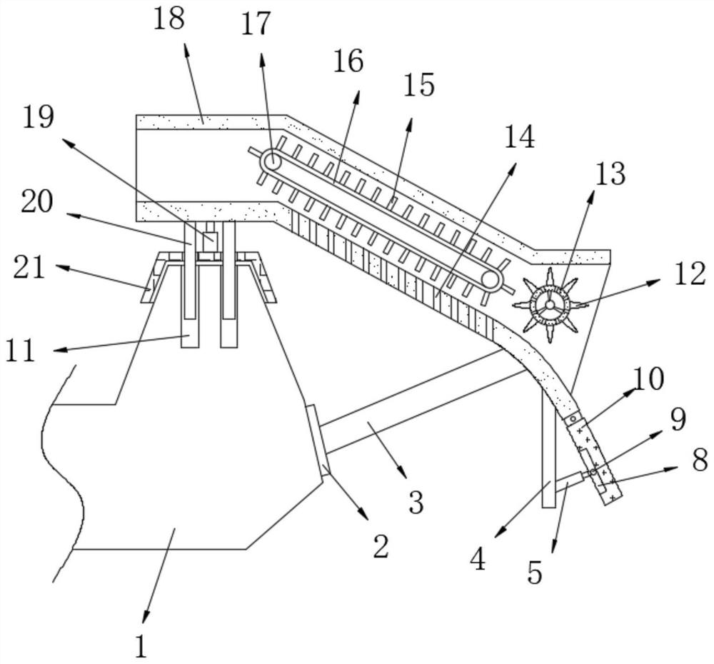
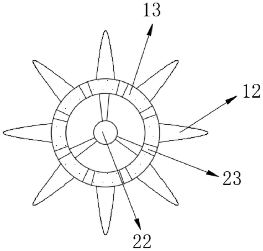
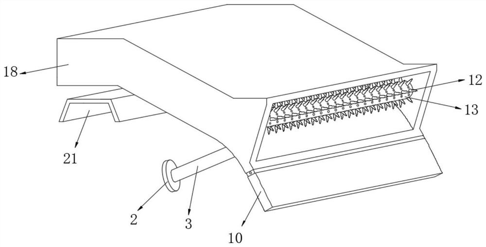
[0028] refer to Figure 1-3 , a floating algae salvage device for water conservancy projects, including a hull 1, four slots 11 distributed in a rectangular shape are opened on the top of the bow of the hull 1, and the insides of the four slots 11 are respectively inserted with limit rods 20, and the four limit rods The top of the rod 20 is connected with the same housing 18 by fastening bolts, the circumference of the four limit rods 20 is sleeved with the same mounting seat 21, and the top outer wall of the mounting seat 21 is connected with a second electric motor by fastening bolts. Telescopic rod 19, the top of the second electric telescopic rod 19 is connected with the bottom outer wall of the housing 18 by fastening bolts, and the inner walls on both sides of the mounting seat 21 are connected with the top of the hull 1 by fastening bolts, and the inner walls on both sides of the housing 18 are There are two conveying rollers 17 connected by bearings, and the same conve...

Embodiment 2

[0036] refer to Figure 4 , a warp knitting machine pulling and coiling device for weaving plastic nets. Compared with Embodiment 1, the side of the movable plate 10 away from the housing 18 is connected with a water pipe 7 through fastening bolts, and the water pipe 7 Evenly distributed water inlet holes are opened on the top outer wall of the water pipe 7. The other side of the water pipe 7 is connected to the water pump 6 through fastening bolts, and the water inlet of the water pump 6 is connected to an extension pipe through a flange. The other end of the extension pipe extends to the water pipe 7. Inside, the outer wall of the water pipe 7 away from the movable plate 10 is hinged with a rubber sheet 24, and the cross section of the rubber sheet 24 is a C-shaped structure. The outer arc surface of 24 is provided with evenly distributed anti-skid bumps.

[0037] Working principle: while the first electric telescopic rod 5 pushes the movable plate 10, the water pump 6 pump...


PUM


Abstract

The invention discloses a floating algae fishing device for water conservancy engineering, which comprises a hull, four slots distributed in a rectangular shape are opened on the top of the bow of the hull, and limit rods are respectively inserted into the inside of the four slots. The top of the limiting rods is provided with the same housing, and the circumferences of the four limiting rods are sleeved with the same mounting seat. The present invention can adjust the position of the shell through the second electric telescopic rod according to the height of the liquid level, and the limit rod and the slot can limit and guide the lifting of the shell, which is practical, flexible and convenient. Drive the conveyor belt to rotate, move the floating algae into the shell upwards, and lift the floating algae to the top of the shell and finally fall into the hull to realize the efficient salvage of the floating algae. At the same time, the first electric telescopic rod can reciprocate and move upwards When the movable plate moves upwards, it moves the rhizomes of the floating algae entering the casing, and can lift the roots of the floating algae to ensure thorough fishing.

Description

technical field [0001] The invention relates to the technical field of water conservancy engineering, in particular to a floating algae fishing device for water conservancy engineering. Background technique [0002] At present, the cleaning of rivers in water conservancy projects mainly relies on manual salvage and chemical herbicides, but manual salvage is inefficient, has a high risk factor, high labor costs, and serious waste of resources. Some deep algae cannot be removed. Chemical herbicides The pollution of water quality is far greater than the pollution of plants such as algae. [0003] After searching, the Chinese patent publication number is the patent of CN206538749U, which discloses a water conservancy project river channel floating algae plant cleaning device, which is characterized in that the installation frame is placed on the arc-shaped baffle, the fixed mount is placed on the arc-shaped baffle, and the crossbar The two ends are respectively fixed on the arc...

Claims


Application Information

Patent Timeline
Patent Type & Authority Patents(China)
IPC IPC(8): E02B15/10
CPCE02B15/10E02B15/104E02B15/103
Inventor 高彩真
Owner 宁夏施能达市政工程有限公司
Learn More