High-speed stirring drilling machine and construction method thereof

A high-speed mixing and drilling rig technology, applied in drilling equipment and methods, rotary drilling rigs, drill pipes, etc., can solve the problems of inconvenient transportation, low work efficiency, serious equipment loss, etc., to reduce construction procedures, improve construction efficiency, cost saving effect

Pending Publication Date: 2020-08-25
BEIJING ZHONGYAN DADI TECH CO LTD
View PDF0 Cites 2 Cited by
  • Summary
  • Abstract
  • Description
  • Claims
  • Application Information

AI Technical Summary

Problems solved by technology

[0003] At present, conventional power heads on the market have complex structures, large volumes, small power, low work efficiency, and inconvenient transportation. In addition, the power heads are generally installed on the top of the drilling rig, and gradually decrease as the drill pipe advances. The weight of the power head Larger, causing the center of gravity of the drilling rig to tilt forward and move up, resulting in greater danger during drilling rig construction
In addition, there are also power heads that are divided into upper and lower parts, one part is responsible for downforce and lifting force at the upper part, and the other part is responsible for providing torque at the lower part, but this structure is more complicated, the construction process is cumbersome, and the equipment loss is serious

Method used


Image

  • High-speed stirring drilling machine and construction method thereof
  • High-speed stirring drilling machine and construction method thereof
  • High-speed stirring drilling machine and construction method thereof

Examples


Embodiment Construction

[0032] Below in conjunction with accompanying drawing and specific embodiment the present invention is described in further detail:

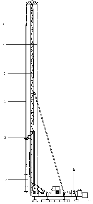
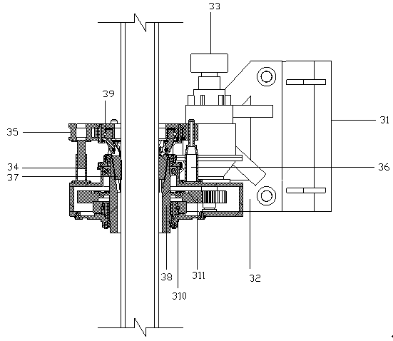
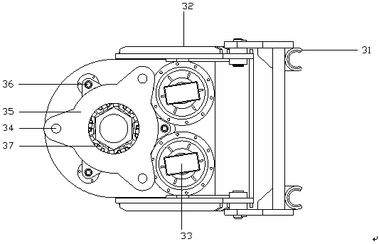
[0033] Such as Figure 1~3As shown, a high-speed mixing drilling rig is characterized in that it includes a pile frame 1, a chassis 2, a vertical rotary power system, a circular rotary power system, a rotary drive 3, a rotary pressure plate 4, a drill rod 5, a drill bit 6, and a chain 7. Solidified material pumping system, high-pressure gas supply system, and control system; the rotary drive 3 includes a guide rail 31, a bracket 32, a hydraulic motor 33, a compression cylinder 34, a connector 35, a limit rod 36, a block 37, Slewing sleeve 38, upper slewing bearing 39, lower slewing bearing 310, gear 311; the pile frame 1 and the chassis 2 are connected by bolts, and the vertical slewing power system and the hoop slewing power system are installed on the chassis 2, The rotary drive 3 is connected to the pile frame 1 through the guide rail 31, th...


PUM


Abstract

The invention discloses a high-speed stirring drilling machine and a construction method thereof, and belongs to the technical field of pile foundation construction. A pile frame, a base plate, a vertical rotation power system, a ring-direction rotation power system, a rotation driver, a rotation pressing disc, a drill rod, a drill bit, a chain, a curing material pumping system and a high-pressuregas supply system are included. The pile frame and the base plate are connected through bolts. The vertical rotation power system and the ring-direction rotation power system are both arranged on thebase plate. The rotation driver 3 is connected with the pile frame through a guide rail, the rotation pressing disc is connected with the vertical rotation power system through the chain, the rotation pressing disc is connected with the drill rod through a flange, the drill rod is connected with the drill bit through a flange, and the curing material pumping system and the high-pressure gas supply system are connected with the drill rod through a high-pressure rubber pipe. Through lower arrangement of a power head, the gravity center of the drilling machine is lowered, and forward tilting ofthe drilling machine in the construction process is prevented; and only through arrangement of one power head, the functions of drill lowering and drill lifting are achieved, the construction procedures are reduced, the construction efficiency is improved, and the cost is saved.

Description

technical field [0001] The invention relates to the technical field of pile foundation construction, in particular to a high-speed mixing drilling machine and a construction method thereof. Background technique [0002] The construction of high-rise buildings, railways or bridges requires piling, and pile holes need to be drilled during piling. According to different geology, piles are poured in the borehole after drilling. This kind of pile is called cast-in-situ pile, or cement slurry is sprayed into the hole while drilling, and the pile is cast on-site. This kind of pile is called mixing pile. Whether it is a cast-in-situ pile or a mixing pile, an engineering drilling rig will be used. The core component of the engineering drilling rig is the power head. The main function of the power head is to transmit the torque and speed generated by the power part to the drilling tool, so as to realize the continuous drilling of the drilling tool and the breaking of rocks and gravel...

Claims


Application Information

Patent Timeline
Patent Type & Authority Applications(China)
IPC IPC(8): E21B3/02E21B7/02E21B7/04E21B19/10E21B19/00E02D5/46
CPCE02D5/46E21B3/02E21B7/02E21B7/04E21B19/00E21B19/10
Inventor 李建平宋伟杰朱庆凯杜英杰刘光磊武思宇
Owner BEIJING ZHONGYAN DADI TECH CO LTD
Why Eureka
Try Eureka