Eureka AIR delivers breakthrough ideas for toughest innovation challenges, trusted by R&D personnel around the world.

Damping shock absorption system for pneumatic valve

A technology of shock absorption system and pneumatic valve, which is applied in the direction of fluid pressure actuation system components, valve details, valve devices, etc., can solve the problems of large noise and vibration, and achieve the effect of reducing noise

Pending Publication Date: 2020-08-25
CHUANBEI VACUUM TECH BEIJING
View PDF0 Cites 0 Cited by
  • Summary
  • Abstract
  • Description
  • Claims
  • Application Information

AI Technical Summary

Problems solved by technology

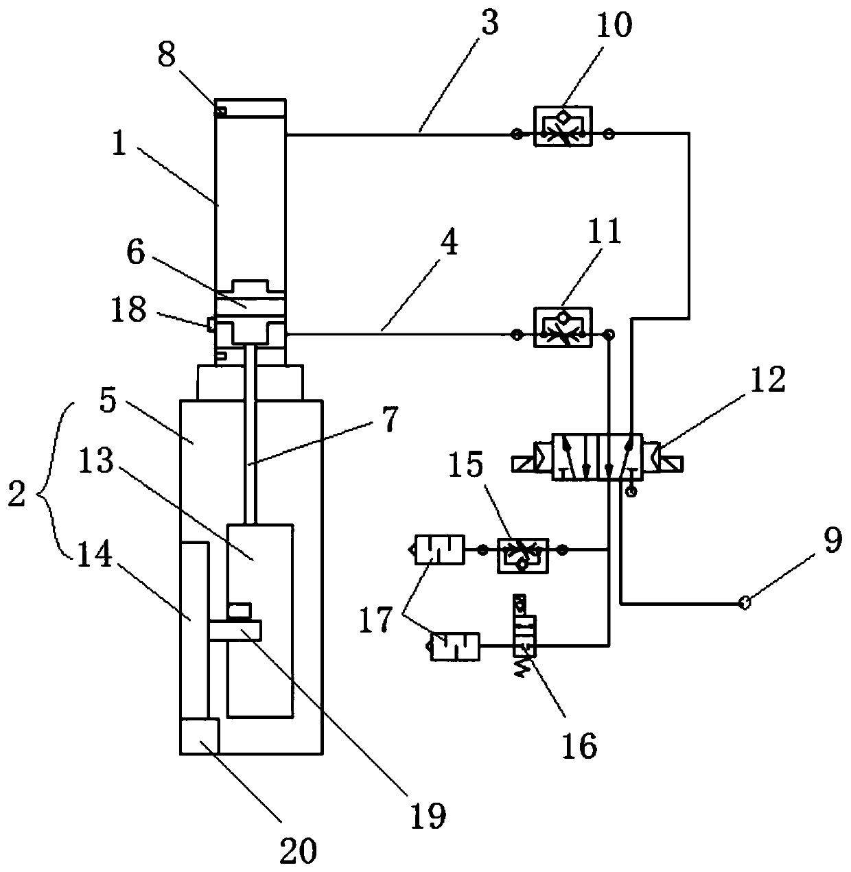
[0004] Therefore, the technical problem to be solved by the present invention is to overcome the defects of large vibration and high noise of the pneumatic valve in the prior art, so as to provide a pneumatic valve damping and shock absorption system

Method used


Image

  • Damping shock absorption system for pneumatic valve
  • Damping shock absorption system for pneumatic valve
  • Damping shock absorption system for pneumatic valve

Examples


Embodiment Construction

[0042] The technical solutions of the present invention will be clearly and completely described below in conjunction with the accompanying drawings. Apparently, the described embodiments are some of the embodiments of the present invention, but not all of them. Based on the embodiments of the present invention, all other embodiments obtained by persons of ordinary skill in the art without making creative efforts belong to the protection scope of the present invention.

[0043] In the description of the present invention, it should be noted that the terms "center", "upper", "lower", "left", "right", "vertical", "horizontal", "inner", "outer" etc. The indicated orientation or positional relationship is based on the orientation or positional relationship shown in the drawings, and is only for the convenience of describing the present invention and simplifying the description, rather than indicating or implying that the referred device or element must have a specific orientation, ...


PUM


Abstract

The invention provides a damping shock absorption system for a pneumatic valve, and belongs to the technical field of gas circuit control. The damping shock absorption system for the pneumatic valve comprises a gas cylinder, a valve and a buffer loop, wherein a piston and a pneumatic rod connected with the piston are arranged in the gas cylinder; a driving rack connected with the pneumatic rod ofthe gas cylinder and a valve plate connected with the driving rack are arranged in the valve; the buffer loop communicates with at least one air vent of the gas cylinder and comprises a first adjusting branch and a second adjusting branch which are connected in parallel, a first one-way speed regulating valve is arranged on the first adjusting branch, and an electromagnetic valve is arranged on the second adjusting branch. According to the damping shock absorption system for the pneumatic valve, when the gas cylinder performs exhausting, gas can pass at a higher speed through the second adjusting branch and can only pass at a lower speed through the first adjusting branch, so that when the piston moves to be close to the place, exhaust gas can pass through the first adjusting branch, the exhausting speed is reduced, and noise produced when the pneumatic valve is closed is reduced.

Description

technical field [0001] The invention relates to the technical field of gas path control, in particular to a pneumatic valve damping and shock absorption system. Background technique [0002] Pneumatic valves have the advantages of simple structure, easy access to air source, high opening and closing speed, and can be directly used in explosion-proof requirements, so that pneumatic valves occupy a stable position in the field of vacuum valves. [0003] However, because the pneumatic valve is driven by gas, the gas is compressible, and the driving speed is not easy to control, so that the pneumatic valve has a large vibration when it is closed. Therefore, the pneumatic valve needs a good damping and shock absorbing device. Contents of the invention [0004] Therefore, the technical problem to be solved by the present invention is to overcome the defects of large vibration and noise of the pneumatic valve in the prior art, so as to provide a damping system for the pneumatic v...

Claims


Application Information

Patent Timeline
IPC IPC(8): F15B15/22F15B15/28F15B15/16F15B21/00F16K31/124F16F15/08B32B27/06B32B27/30B32B27/40B32B25/08
CPCB32B25/08B32B27/06B32B27/304B32B27/40B32B2250/05B32B2327/18F15B15/1423F15B15/22F15B15/2861F15B21/001F15B21/008F15B2211/755F16F15/08F16K31/1245
Inventor 庞云玲杨恩哲张魁榜马现刚陈林
Owner CHUANBEI VACUUM TECH BEIJING
Why Eureka
Eureka Blog
Learn More