Method for quickly extracting mid-span displacement influence line of vehicle slowly passing through simply supported beam bridge

A technology of displacement influence lines and simply supported beam bridges, applied in special data processing applications, instruments, electrical digital data processing, etc., can solve problems such as unclear mechanical concepts, difficult to obtain theoretical values, and inability to compare with measured values

Active Publication Date: 2020-08-25
HARBIN INST OF TECH
View PDF9 Cites 2 Cited by
  • Summary
  • Abstract
  • Description
  • Claims
  • Application Information

AI Technical Summary

Problems solved by technology

[0006] The purpose of the present invention is to provide a method for quickly extracting the displacement influence line of a vehicle slowly passing through the mid-span of a simply supported girder bridge in order to solve the problems that the concept of mechanics is not clear and it is difficult to obtain the measured value of the influence line in the existing quasi-static load test. The mid-span displacement

Method used


Image

  • Method for quickly extracting mid-span displacement influence line of vehicle slowly passing through simply supported beam bridge
  • Method for quickly extracting mid-span displacement influence line of vehicle slowly passing through simply supported beam bridge
  • Method for quickly extracting mid-span displacement influence line of vehicle slowly passing through simply supported beam bridge

Examples


specific Embodiment approach 1

[0085] Specific embodiment 1: This embodiment records a method for quickly extracting the displacement influence line of a vehicle slowly passing through the mid-span of a simply supported girder bridge. The driving speed of the vehicle is less than 5km / h. For a three-axle truck, the method is as follows:

[0086] Situation 1: Influence line of mid-span displacement under the action of double-axle truck

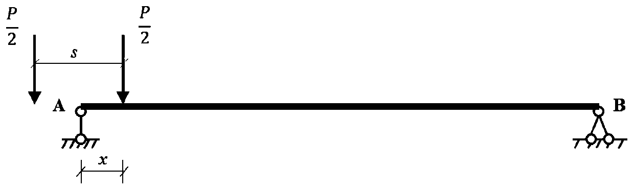
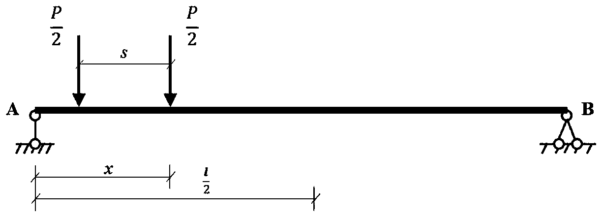
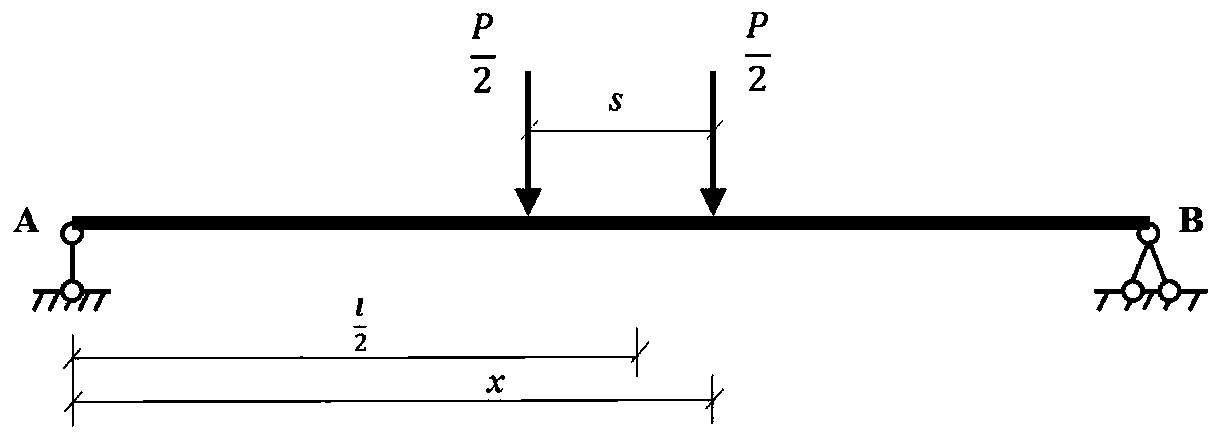
[0087] For the corresponding two-axle truck, the axle loads of the front axle and the rear axle are P / 2 respectively, the total weight is P, and the wheelbase is s; the distance from the front axle to the left fulcrum of the bridge is x 1 =x, the distance x from the rear axle to the left fulcrum of the bridge 2 =x-s;

[0088] The mid-span vertical displacement formula is as follows:

[0089] Ⅰ.xfigure 1 )

[0090]

[0091] Ⅱ. ( figure 2 )

[0092]

[0093] Ⅲ. ( image 3 )

[0094]

[0095] IV. ( Figure 4 )

[0096]

[0097] In the above formul...

Embodiment 1

[0143] A method for quickly extracting the displacement influence line of a vehicle slowly passing through the mid-span of a simply supported beam bridge. The specific application steps are shown in Figure 11:

[0144] Two-axle trucks pass slowly across the bridge. Calculate the concrete simply supported beam bridge with a span of l=40m. The two-axle trucks pass slowly through the bridge. The total weight of the vehicle is P=300kN, and the weights of the corresponding front and rear axles are both P 1 =P 2 =150kN, wheelbase s=3m.

[0145] The displacement sensor is arranged across the section, and its displacement curve is as follows Figure 12 As shown, the mid-span vertical displacement influence line obtained after separation by this method is as follows: Figure 13 As shown, through the finite element model analysis, the theoretical value of the mid-span vertical displacement influence line is as follows: Figure 14 As shown, comparing the two, the relative error is as ...

Embodiment 2

[0147] Three-axle trucks pass slowly across the bridge. Calculate the concrete simply supported beam bridge with a span of l=40m. Two-axle trucks pass slowly through the bridge. The total weight of the vehicle is P=300kN, and the corresponding weight of the front axle is P 1 =60kN, the weight of the center axle and the rear axle are both P 2 =P 3 =120kN, the distance from the front axle to the middle axle s 1 =4m, distance s from central axis to rear axle 2 = 1.4m.

[0148] The displacement sensor is arranged across the section, and its displacement curve is as follows Figure 16 As shown, the mid-span vertical displacement influence line obtained after separation by this method is as follows: Figure 17 As shown, through the finite element model analysis, the theoretical value of the mid-span vertical displacement influence line is as follows: Figure 14 As shown, comparing the two, the relative error is as Figure 18 As shown, it can be seen that for the section near t...


PUM


Abstract

The invention discloses a method for quickly extracting mid-span displacement influence lines of vehicles slowly passing through a simply supported beam bridge, and belongs to the technical field of bridge detection methods. The objective of the invention is to solve the problems of unclear mechanical concept and difficulty in obtaining an influence line measured value in an existing quasi-staticload test. According to the method, effective separation is carried out on a midspan displacement curve actually measured on site, the midspan displacement curve is compared with a theoretical influence line, quick evaluation work of the technical state of the bridge can be achieved, and the technical problem that in the quasi-static load test process, a theoretical value is not easy to obtain during data processing, and consequently the theoretical value cannot be compared with an actually-measured value can be effectively solved. The bridge state quick evaluation method based on the displacement influence line is clear, and the mechanical concept is clear; by means of the method, the displacement curves under the action of the multiple axles can be quickly converted into the structure influence lines, the structure influence lines can be directly compared with theoretical values, the operability of the method is improved, and then quick and accurate evaluation of the bridge state isachieved.

Description

technical field [0001] The invention belongs to the technical field of bridge detection methods, and in particular relates to a method for quickly extracting displacement influence lines of vehicles slowly passing through the mid-span of simply supported beam bridges. Background technique [0002] According to the "Statistical Bulletin on the Development of the Transportation Industry in 2018", as of the end of 2018, my country has built about 851,500 highway bridges, and has become a veritable bridge country. With the vigorous development of my country's transportation industry, the safety of bridge structures is the key to communication across the board. However, with the increase of the service time of existing bridges, the continuous increase of traffic load and the long-term effect of natural environmental factors, as well as the update of design codes in different periods, most of the small and medium-span bridges bear the influence of high vehicle load effects, which ...

Claims


Application Information

Patent Timeline
IPC IPC(8): G06F30/15G06F30/13G06F119/14
CPCG06F30/13G06F30/15G06F2119/14
Inventor 高庆飞武彪刘洋李钧
Owner HARBIN INST OF TECH
Why Eureka
Try Eureka