Rapid mixing magnetic stirrer and working method thereof

A magnetic stirrer and magnetic stirring technology, applied to chemical instruments and methods, mixers, mixer accessories, etc., can solve the problems of not easy to fix the stirring container, difficult to drive the upper stirring, slow stirring speed, etc., to expand the scope of use, Effects that cost less to apply and speed up mixing

Pending Publication Date: 2020-08-28
SUZHOU BEIKAI BIOCHEM EQUIP
View PDF0 Cites 3 Cited by
  • Summary
  • Abstract
  • Description
  • Claims
  • Application Information

AI Technical Summary

Problems solved by technology

[0003] In the process of using the existing magnetic stirrer, when the stirring container is used for magnetic stirring, the stirring container is directly placed on the top of the device, it is not easy to fix the stirring container, and it is only stirred by the stirring bar. The generated vortex is difficult to drive the upper part to stir, it takes a long time, the efficiency is low, and the stirring speed is slow

Method used


Image

  • Rapid mixing magnetic stirrer and working method thereof
  • Rapid mixing magnetic stirrer and working method thereof

Examples


Embodiment 1

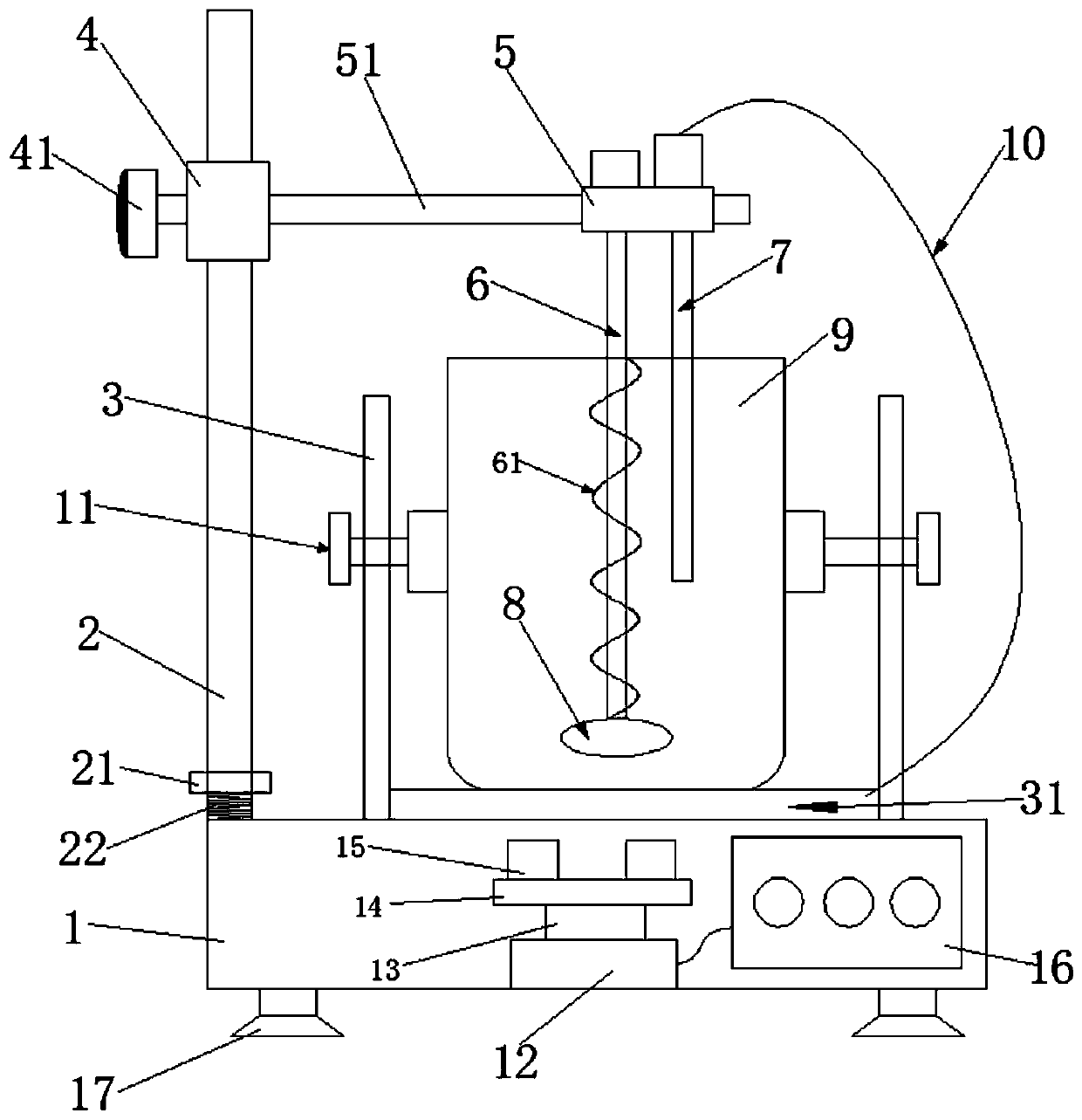
[0026] Such as figure 1 The fast-mixing magnetic stirrer shown includes a magnetic stirrer body 1. A pole 2 is provided on the upper surface of the left end of the magnetic stirrer body 1, and a first sliding seat 4 is provided on the upper end of the pole 2. A sliding seat 4 is provided with a fastening bolt 41 for fixing its position on the vertical pole, the first sliding seat 4 is sleeved with a cross bar 51, and the other end of the cross bar 51 is provided with a second sliding seat 5 , A stirring rod 6 and a temperature sensor 7 are vertically sleeved in the second sliding seat 5, a magnetic stirring bar 8 is arranged at the bottom of the stirring rod 6, and a motor 12 is arranged in the magnetic stirrer body 1. The top of 12 is connected with a supporting plate 14 through a rotating shaft 13, a high-temperature magnet 15 is fixedly installed on the supporting plate 14, and the motor 12 is connected to a control box 16 in parallel;

[0027] Wherein, the upper surface of th...

Embodiment 2

[0033] The magnetic stirrer body 1, the upper surface of the left end of the magnetic stirrer body 1 is provided with a vertical rod 2, the upper end of the vertical rod 2 is provided with a first sliding seat 4, and the first sliding seat 4 is provided for fixing it on The fastening bolt 41 on the upright position, the first sliding seat 4 is sleeved with a cross bar 51, the other end of the cross bar 51 is provided with a second sliding seat 5, and the second sliding seat 5 is vertically sleeved A stirring rod 6 and a temperature sensor 7 are provided, the bottom of the stirring rod 6 is provided with a magnetic stirrer 8, the magnetic stirrer body 1 is provided with a motor 12, and the top of the motor 12 is connected with a support plate 14 through a rotating shaft 13 , A high temperature magnet 15 is fixedly installed on the support plate 14, and the motor 12 is connected to the control box 16 in parallel;

[0034] Wherein, the upper surface of the magnetic stirrer body 1 is...


PUM


Abstract

The invention discloses a rapid mixing magnetic stirrer which comprises a magnetic stirrer body; a vertical rod is arranged on the upper surface of the left end of the magnetic stirrer body; a first sliding seat is arranged at the upper end of the vertical rod; a cross rod is arranged in the first sliding seat in a sleeving manner; a second sliding seat is arranged at the other end of the cross rod; a stirring rod and a temperature sensor are vertically sleeved with the second sliding base, a magnetic stirrer is arranged at the bottom of the stirring rod, a motor is arranged in the magnetic stirrer body, the top of the motor is connected with a supporting plate through a rotating shaft, a high-temperature magnet is fixedly installed on the supporting plate, and the motor is connected witha control box in parallel. According to the magnetic stirrer capable of achieving rapid mixing, the container is fixed to the upper portion of the magnetic stirrer through the clamping groove, the container is prevented from rotating together, the magnetic field drives the stirrer to rotate, the stirrer rotates to drive the stirring rod to rotate, the adjusting assembly can use containers with different capacities, and the application range of the magnetic stirrer is enlarged.

Description

Technical field [0001] The invention belongs to the technical field of magnetic stirrers, and specifically relates to a fast-mixing magnetic stirrer and a working method thereof. Background technique [0002] Magnetic stirrer is a laboratory instrument used for liquid mixing, mainly used for stirring or simultaneously heating and stirring liquid or solid-liquid mixtures with low viscosity. The basic principle is to use the principle of repulsion of the same sex and attraction of the opposite sex of the magnetic field, and use the magnetic field to push the magnetic stirrer placed in the container to rotate in a circle, so as to achieve the purpose of stirring the liquid. [0003] In the process of using the existing magnetic stirrer, when the stirring container is used for magnetic stirring, the stirring container is directly placed on the top of the device. It is not easy to fix the stirring container, and it is only stirred by the stirring bar. The generated vortex is difficult ...

Claims


Application Information

Patent Timeline
Patent Type & Authority Applications(China)
IPC IPC(8): B01F13/08B01F15/00
CPCB01F33/4537B01F35/2115B01F35/324B01F35/2215B01F35/413B01F35/42B01F35/43
Inventor 许红玲
Owner SUZHOU BEIKAI BIOCHEM EQUIP
Why Eureka
Try Eureka