Aluminum alloy fixing device with outer wall clamping and inner wall supporting functions

A fixing device and aluminum alloy technology, which is applied in the field of aluminum alloy, can solve the problems of material shaking, concentrated force, insufficient support on the inner wall of aluminum tube, etc., and achieve the effects of alleviating stress concentration, suppressing local deformation, and ensuring stability

Active Publication Date: 2020-08-28
重庆世茂机械制造有限公司
View PDF8 Cites 7 Cited by
  • Summary
  • Abstract
  • Description
  • Claims
  • Application Information

AI Technical Summary

Problems solved by technology

[0003] In the process of making aluminum alloy, processing such as punching or cutting is often carried out. In order to ensure the stability of processing, it is generally necessary to clamp the aluminum tube. There are generally two methods in the process of clamping. One is manual stabilization, and because the material will shake violently during processing, manual clamping is more laborious. The other is to use a clamp to fix the outside of the aluminum tube, and the traditional clamp design is relatively simple. During the clamping process, there is not enough support on the inner wall of the aluminum tube, which may cause the inside of the aluminum tube to be out of round, and there will be a phenomenon of concentrated force during processing. In severe cases, the aluminum tube will be deformed. If the error is large, it even needs to be rebuilt, which will waste a lot of manpower and material resources
[0004] In order to solve the above problems, the inventor proposed an aluminum alloy fixing device with outer wall clamping and inner wall support. When fixing, support the inner wall of the pipeline to further ensure the stability of the pipeline, and at the same time avoid deformation caused by pipeline processing

Method used


Image

  • Aluminum alloy fixing device with outer wall clamping and inner wall supporting functions
  • Aluminum alloy fixing device with outer wall clamping and inner wall supporting functions
  • Aluminum alloy fixing device with outer wall clamping and inner wall supporting functions

Examples


Embodiment Construction

[0024] The following will clearly and completely describe the technical solutions in the embodiments of the present invention with reference to the accompanying drawings in the embodiments of the present invention. Obviously, the described embodiments are only some, not all, embodiments of the present invention. Based on the embodiments of the present invention, all other embodiments obtained by persons of ordinary skill in the art without making creative efforts belong to the protection scope of the present invention.

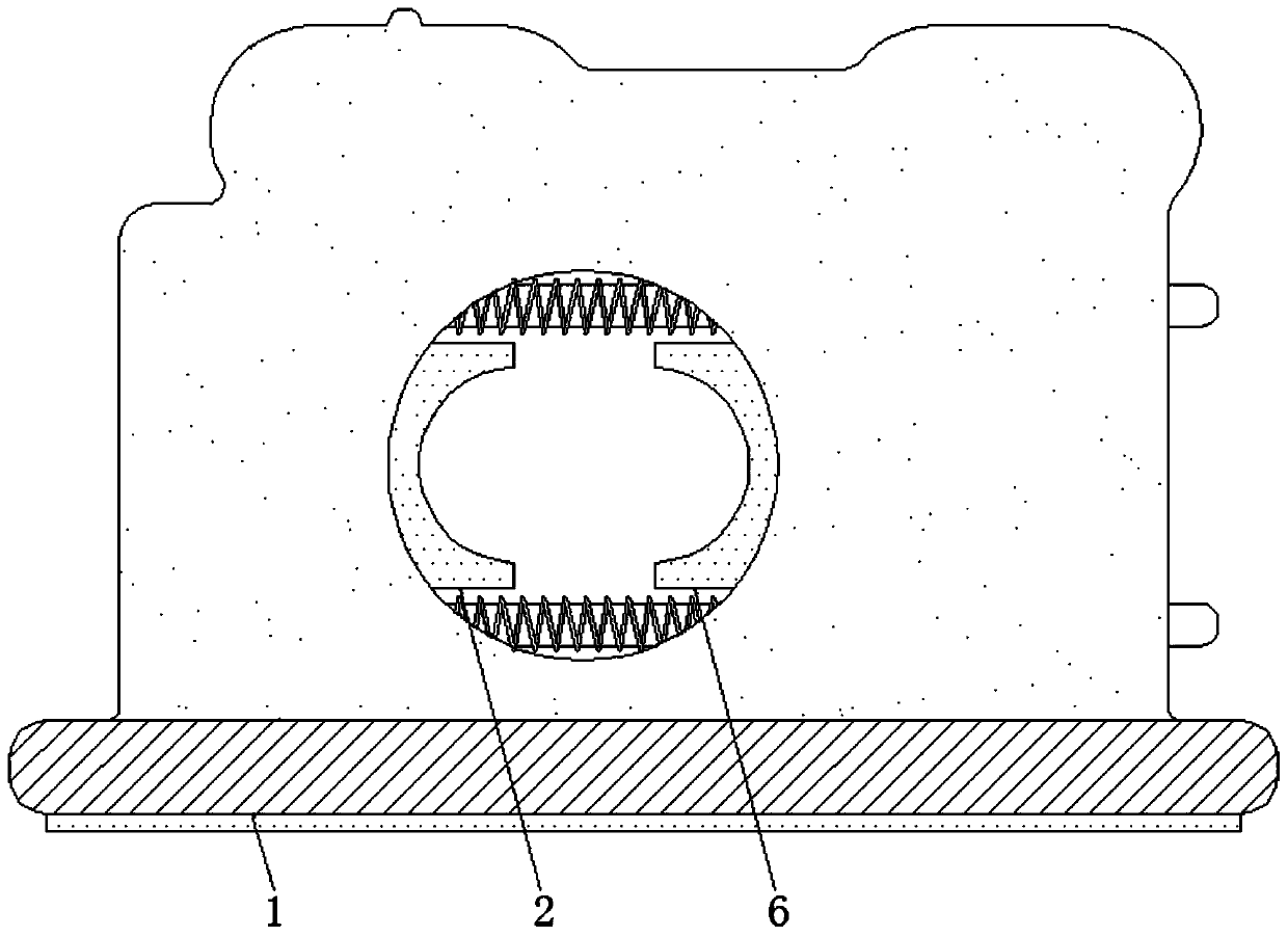
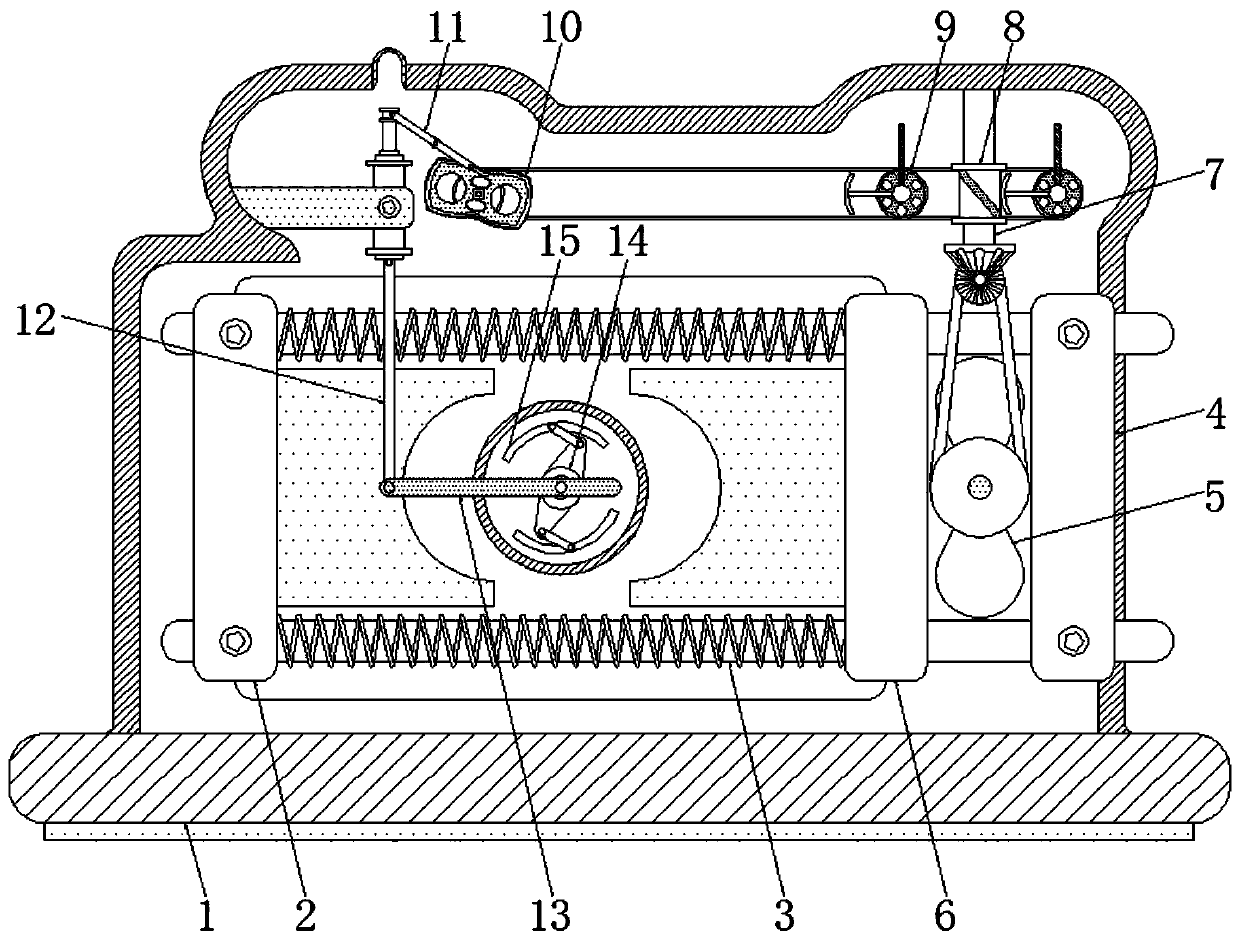
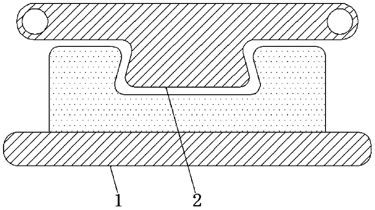
[0025] see Figure 1-5 , an aluminum alloy fixing device clamped by the outer wall and supported by the inner wall, including a base 1, the whole device is supported by the base 1, thereby ensuring the stability of the whole device, a first splint 2 is movably connected on the top of the base 1, and the first splint 2 is used to A splint 2 clamps the left end of the circular aluminum alloy. The specifications of the first splint 2 and the second splint 6 are c...


PUM


Abstract

The invention relates to the technical field of aluminum alloy, and discloses an aluminum alloy fixing device with outer wall clamping and inner wall supporting functions. The aluminum alloy fixing device comprises a base. The base is used for supporting the whole device, through cooperative use of a first clamping plate, a transverse rod, a limiting rod, a first rotary disc and a second clampingplate, the outer side of aluminum alloy can be fixed, therefore, the stability of the aluminum alloy during machining is guaranteed, the aluminum alloy can be automatically loosened after machining iscompleted, and the intelligence of the whole device is improved; through cooperative use of a disc and a sleeve rod, the inner wall is supported while the outer side of the aluminum alloy is clamped,deformation of the tubular inner wall is prevented, the phenomenon of stress concentration is relieved, finally, local deformation caused by material extension and stress concentration is restrained,through cooperative use of a special-shaped disc, a first supporting rod and a vertical rod, two steps of clamping on the outer side and supporting on the inner wall are linked, therefore, the linkage performance of the whole device is improved, and the operation is easier.

Description

technical field [0001] The invention relates to the technical field of aluminum alloys, in particular to an aluminum alloy fixing device clamped by an outer wall and supported by an inner wall. Background technique [0002] Aluminum alloy is the most widely used non-ferrous metal structural material in the industry. It has been widely used in aviation, aerospace, automobile, machinery manufacturing, marine aluminum alloy and chemical industry, and has very broad development prospects. [0003] In the process of making aluminum alloy, processing such as punching or cutting is often carried out. In order to ensure the stability of processing, it is generally necessary to clamp the aluminum tube. There are generally two methods in the process of clamping. One is manual stabilization, and because the material will shake violently during processing, manual clamping is more laborious. The other is to use a clamp to fix the outside of the aluminum tube, and the traditional clamp de...

Claims


Application Information

Patent Timeline
Patent Type & Authority Applications(China)
IPC IPC(8): B23Q3/06B25B11/00
CPCB23Q3/064B25B11/00
Inventor 汪金桥
Owner 重庆世茂机械制造有限公司
Why Eureka
Try Eureka