Sheet extrusion die head
A technology for extruding die heads and sheets, applied in the field of molds, can solve problems such as the inability to fine-tune the thickness of products at the die opening, and achieve the effects of precise axial positioning, good adjustment accuracy and precise precision.
- Summary
- Abstract
- Description
- Claims
- Application Information
AI Technical Summary
Problems solved by technology
Method used
Image
Examples
Embodiment 1
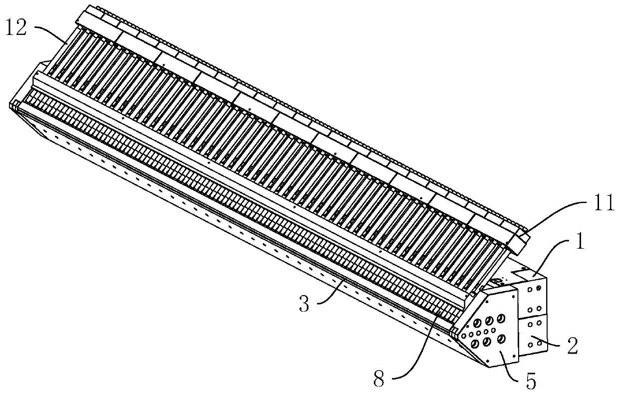
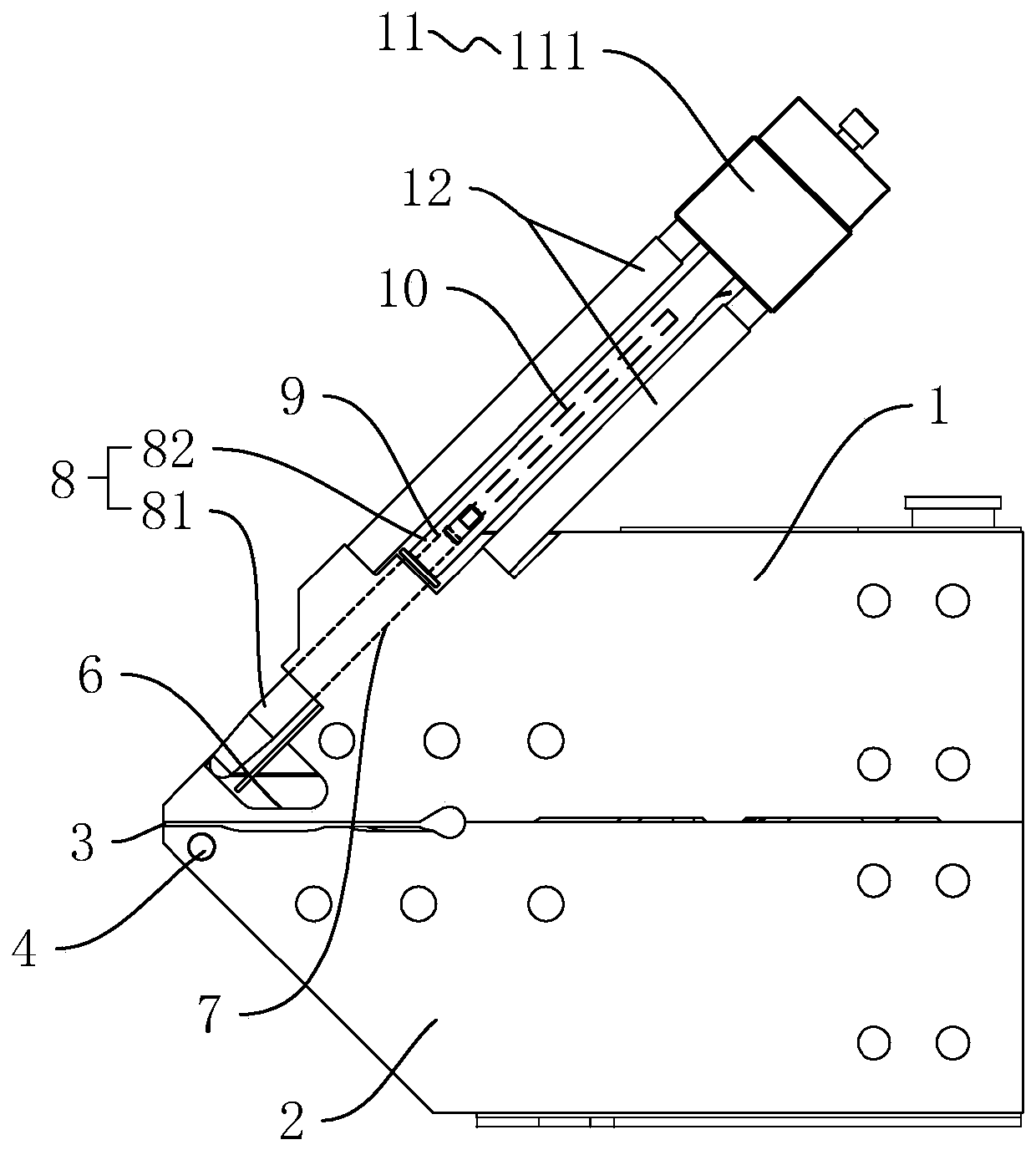
[0038] A sheet extrusion die, such as figure 1 , figure 2As shown, it includes an upper die body 1 with an upper die lip and a lower die body 2 with a lower die lip, and the upper die lip and the lower die lip are spliced to form a die lip gap 3 . Both the upper mold body 1 and the lower mold body 2 are provided with heating pipes (not shown). The heating pipes heat the temperature of the mold by energizing. Usually, a temperature sensor is connected to the corresponding heating pipes to precisely control the heating temperature of the heating pipes. A heating oil circuit 4 is opened laterally along the lower die body 2 at the outlet end of the lower die body 2 near the die lip gap 3 , and the heating oil circuit 4 can heat the outlet of the die lip gap 3 through the heating oil. In actual use, after the upper mold body 1 and the lower mold body 2 are spliced, the lateral sides of the upper mold body 1 and the lower mold body 2 are fixed by the fixing plate 5 to cover the ...
Embodiment 2
[0043] A sheet extrusion die head differs from Embodiment 1 in that the structure of the stopper 11 is different.
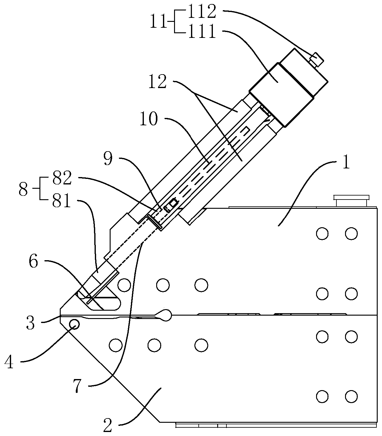
[0044] Such as image 3 As shown, the limiting member 11 includes a limiting seat 111 and a limiting bolt 112 . The limit seat 111 is fixed on the upper mold body 1 through the connecting rod 12 , and the limit seat 111 is located at the end of the expansion tube 82 away from the adjustment rod 81 . The number and position of the limit bolts 112 are set in one-to-one correspondence with the expansion adjusting member 8 . The limit bolt 112 is threaded on the limit seat 111, and the limit bolt 112 is coaxially arranged with the corresponding expansion tube 82. The limit bolt 112 is located at the end of the expansion tube 82 away from the adjustment rod 81 and is pressed against the expansion tube 82 away from The end of the rod 81 is adjusted to limit the position of the expansion tube 82 .
[0045] When the expansion adjustment member 8 is installed, the limi...
Embodiment 3
[0047] A sheet extrusion die head, the difference from Embodiment 1 is that the structures of the expansion tube 82 and the stopper 11 are different.
[0048] Such as Figure 4 , Figure 5 As shown, the expansion tube 82 includes a tube body 821 coaxially arranged on the adjustment rod 81 and a limit column 822 coaxially arranged at the end of the tube body 821 away from the adjustment rod 81 , and the heating rod 10 is located inside the tube body 821 . One end of the tube body 821 close to the limiting column 822 is provided with a wiring groove 13 , and the wiring groove 13 is arranged radially through the side wall of the tube body 821 for the wires of the heating rod 10 to pass through. The limit column 822 is a cylinder and is set equal to the diameter of the tube body 821. The limit column 822 is coaxially fixed with a positioning column 14 near the end face of the tube body 821. The positioning column 14 is coaxially inserted into the tube body 821 so that the limit c...
PUM
 Abstract
Description
Claims
Application Information
 - R&D Engineer
- R&D Manager
- IP Professional
- Industry Leading Data Capabilities
- Powerful AI technology
- Patent DNA Extraction
Browse by: Latest US Patents, China's latest patents, Technical Efficacy Thesaurus, Application Domain, Technology Topic, Popular Technical Reports.
© 2024 PatSnap. All rights reserved.Legal|Privacy policy|Modern Slavery Act Transparency Statement|Sitemap|About US| Contact US: help@patsnap.com


