
High-reduction-efficiency reducer exclusive to tension leveling of continuous casting machine

A deceleration efficiency, continuous casting machine technology, applied in the direction of electromechanical devices, mechanical equipment, control mechanical energy, etc., can solve the problems of poor deceleration efficiency, etc., to achieve the effect of increasing use efficiency, fast and convenient use

Pending Publication Date: 2020-08-28
TIANJIN CORE PRECISION MECHANICAL ELECTRIC EQUIP
View PDF0 Cites 2 Cited by
  • Summary
  • Abstract
  • Description
  • Claims
  • Application Information

AI Technical Summary

Problems solved by technology

[0005] Aiming at the deficiencies of the prior art, the present invention provides a special reducer for continuous casting machine tensioning and straightening with high deceleration efficiency, which has the advantages of high deceleration efficiency and solves the problem of poor deceleration efficiency

Method used


Image

  • High-reduction-efficiency reducer exclusive to tension leveling of continuous casting machine
  • High-reduction-efficiency reducer exclusive to tension leveling of continuous casting machine
  • High-reduction-efficiency reducer exclusive to tension leveling of continuous casting machine

Examples


Embodiment Construction

[0021] The following will clearly and completely describe the technical solutions in the embodiments of the present invention with reference to the accompanying drawings in the embodiments of the present invention. Obviously, the described embodiments are only some, not all, embodiments of the present invention. Based on the embodiments of the present invention, all other embodiments obtained by persons of ordinary skill in the art without making creative efforts belong to the protection scope of the present invention.

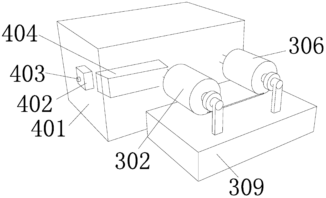
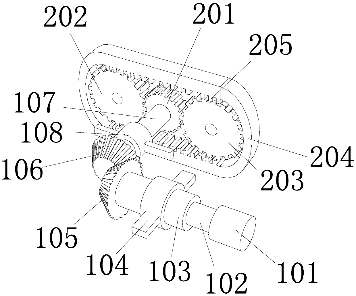
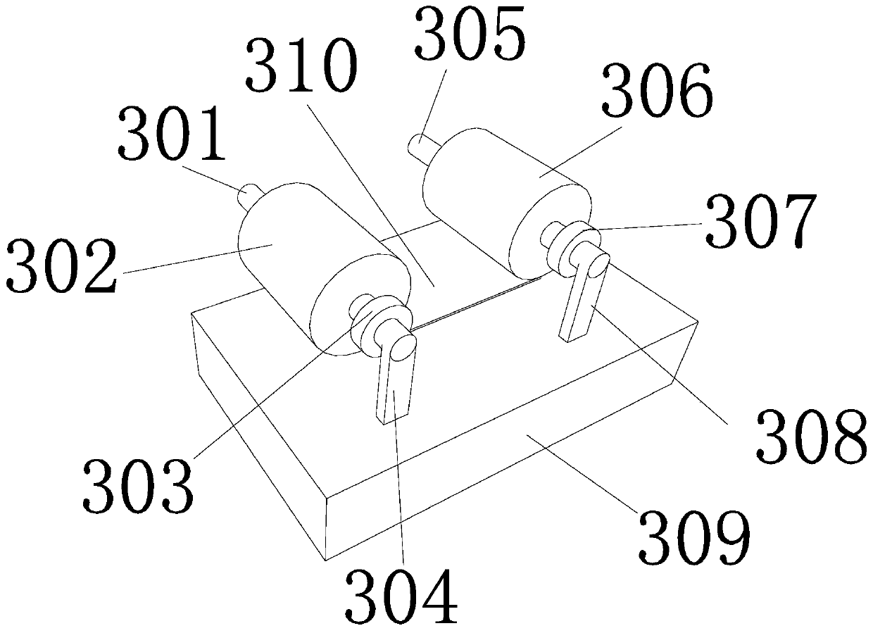
[0022] see Figure 1-4 , the present invention provides the following technical solution: a special reducer for stretching and straightening of a continuous casting machine with high deceleration efficiency, including a driving device 1, a transmission device 2, a rotating device 3 and a control device 4, the driving device 1 includes a motor 101, and the The motor 101 is provided with a motor rotating shaft 102, the left side of the motor rotating shaft 102 i...


PUM


Abstract

The invention relates to the technical field of mechanical equipment, and discloses a high-reduction-efficiency reducer exclusive to tension leveling of a continuous casting machine. The reducer comprises a driving device, a transmission device, a rotating device and a controlling device. The driving device comprises a motor; a motor rotating shaft is arranged on the motor; a transmission shaft Iis fixedly connected with the left side face of the motor rotating shaft; a conical gear I is fixedly connected with the left side face of the transmission shaft I; a conical gear II is engaged with the conical gear I; a transmission shaft II is fixedly connected with the rear side face of the conical gear II; a fixing sleeve ring I is connected with the circumferential surface of the transmissionshaft II in a penetrating mode; the transmission device comprises a gear I and a track; a transmission shaft II is fixedly connected with the front side face of the gear I; a gear II and a gear III are engaged with the gear I; a toothed groove is formed in the inner side face of the track; and the gear II and the gear III are engaged with the toothed groove. When the motor is initiated, the rotating direction of the gear II and the gear III is opposite to the rotating direction of the motor rotating shaft I and a motor rotating shaft II, so rapid reduction of equipment is realized.

Description

technical field [0001] The invention relates to the technical field of mechanical equipment, in particular to a special speed reducer for stretching and straightening of continuous casting machines with high speed reduction efficiency. Background technique [0002] The production process of continuously casting high-temperature molten steel into a billet with a certain cross-sectional shape and a certain size specification is called continuous steel casting, and the equipment required to complete this process is called continuous casting equipment. The electromechanical and hydraulic integration of steel pouring equipment, continuous casting machine body equipment, cutting area equipment, dummy bar collection and conveying equipment constitutes the core part of continuous steel casting equipment, which is customarily called continuous casting machine and the production process of continuous casting machine. Continuously pour high-temperature molten steel into one or a group ...

Claims


Application Information

Patent Timeline
IPC IPC(8): F16H37/02F16H57/035F16H57/038H02K7/00H02K7/116B22D11/12
CPCB22D11/12F16H37/02F16H57/035F16H57/038F16H2057/02034F16H2057/02069H02K7/003H02K7/1163
Inventor 郭凤武
Owner TIANJIN CORE PRECISION MECHANICAL ELECTRIC EQUIP
Learn More