
Heat pump type solution humidifying air treatment device

An air treatment device, heat pump technology, applied in heating methods, household heating, air conditioning systems, etc., can solve the problems of inability to achieve temperature control, human health adjustment, limited humidification range, and different indoor air humidity, etc. Avoid the effects of uneven distribution, clean energy utilization, and even distribution of water vapor

Active Publication Date: 2020-08-28
纽爱新能源(广州)有限公司
View PDF5 Cites 0 Cited by
  • Summary
  • Abstract
  • Description
  • Claims
  • Application Information

AI Technical Summary

Problems solved by technology

If this limit is exceeded, the excess water vapor will condense from the air and form fog. However, in the existing living environment, the ambient air humidity of most people is very low, which makes people often feel dry skin. The humidification range of the humidifier in the prior art is limited, and the moisture is easy to accumulate in a small area after being discharged into the air, which makes the indoor air humidity different, and the humidifier of the prior art can only achieve the effect of humidifying the air, but cannot Realize the function of temperature control and human health regulation, so people need a heat pump type solution humidity control air treatment device to solve the above problems

Method used


Image

  • Heat pump type solution humidifying air treatment device
  • Heat pump type solution humidifying air treatment device
  • Heat pump type solution humidifying air treatment device

Examples


Embodiment

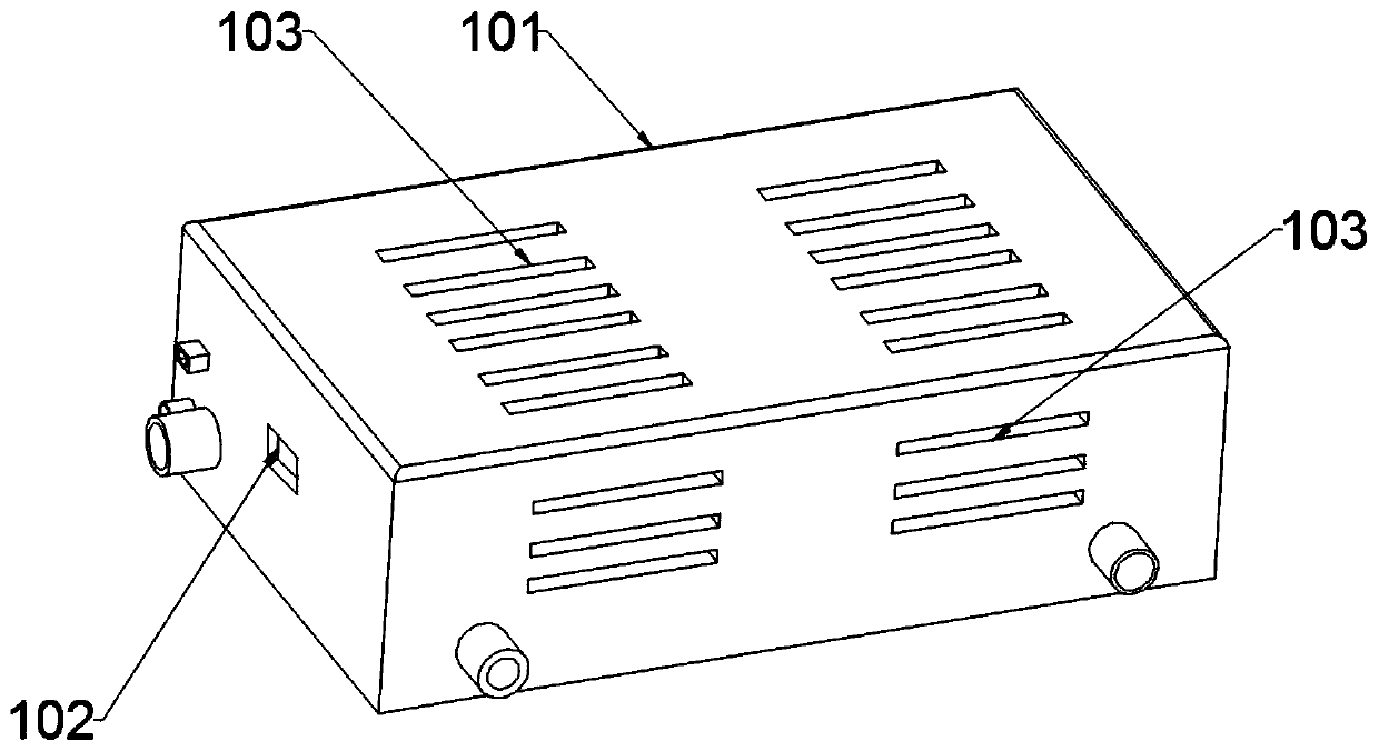
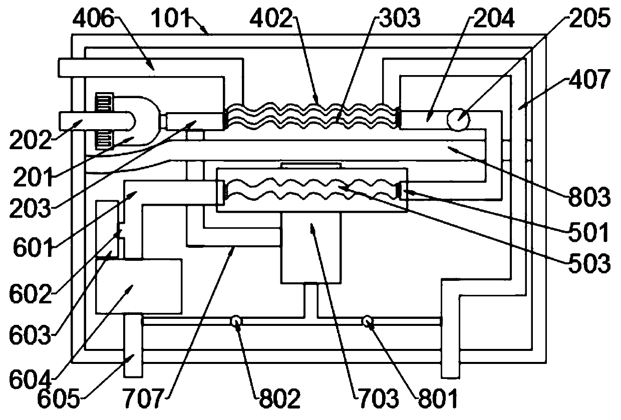
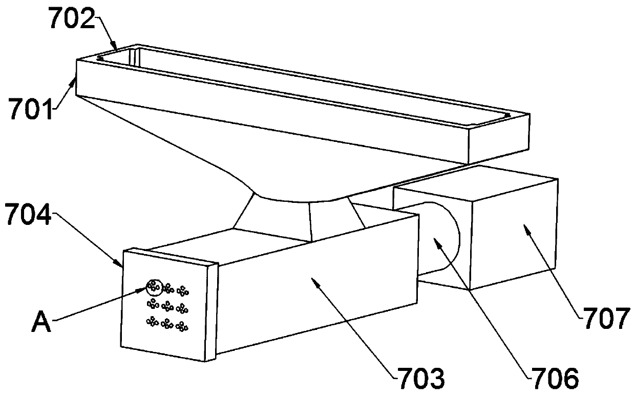
[0029] Example: such as Figure 1-7 As shown, a heat pump type solution humidity control air treatment device includes a shell assembly, a pressure assembly, a heating assembly, a temperature mixing assembly, a cooling assembly, a diffusion assembly, a humidification assembly, and an auxiliary assembly. The shell assembly is located at the end of the entire device On the outside, it plays the role of supporting other components. One end of the shell assembly is equipped with a pressure assembly. The pressure assembly plays the role of heating up the compressed air. One end of the pressure assembly is provided with a heating assembly. The heating assembly plays the role of expanding the range of thermal influence. , a temperature mixing component is installed on the side of the heating component, and the temperature mixing component plays the role of absorbing the heat of the heating component. Components, the diffusion component plays the role of expanding air, the bottom of t...


PUM


Abstract

The invention discloses a heat pump type solution humidifying air treatment device, and belongs to the technical field of air humidity control. The heat pump type solution humidifying air treatment device comprises a shell assembly, a pressure assembly and a heating assembly, wherein the shell assembly is positioned on the outermost side of the whole device, the pressure assembly is arranged at one end of the interior of the shell assembly, and the heating assembly is arranged at one end of the pressure assembly. The heat pump type solution humidifying air treatment device is scientific, reasonable and safe and convenient to use; air temperature adjustment of different pipelines is achieved in an air state conversion mode, so that the temperature control effect of an air conditioner is achieved, and the indoor environment is warm in winter and cool in summer; and the content of negative oxygen ions in exhausted air is increased, the air is guided into a room, and mixing of the negativeoxygen ions is beneficial to human health on the basis of achieving the indoor cooling or heating effect. According to the heat pump type solution humidifying air treatment device, generated condensate water is fully utilized, after the condensate water is mixed with the air containing the negative oxygen ions, water vapor entering the room is distributed more evenly, and the phenomenon that moisture is distributed in a centralized mode and is distributed unevenly is effectively avoided.

Description

technical field [0001] The invention relates to the technical field of air humidity control, in particular to a heat pump type solution humidity control air processing device. Background technique [0002] Air humidification is an effective way to artificially adjust the humidity of the home environment, industrial environment and health care environment. At a certain temperature, the amount of water vapor that can be accommodated in a certain amount of air is limited. When it reaches the maximum, it can no longer absorb water. The air at this time is called saturated air, and the humidity of saturated air is called saturated humidity. If this limit is exceeded, the excess water vapor will condense from the air and form fog. However, in the existing living environment, the ambient air humidity of most people is very low, which makes people often feel dry skin. The humidification range of the humidifier in the prior art is limited, and the moisture is easy to accumulate in a...

Claims


Application Information

Patent Timeline
IPC IPC(8): F24F1/028F24F1/029F24F1/0323F24F1/0353F24F1/037F24F1/039F24F13/22
CPCF24F13/222F24F1/028F24F1/029F24F1/0323F24F1/0353F24F1/037F24F1/039
Inventor 潘江川
Owner 纽爱新能源(广州)有限公司
Learn More