
USB clock generation circuit
A clock generation circuit and circuit technology, applied in the direction of electrical digital data processing, instruments, etc., can solve the problems of slow start of crystal oscillator, limited product flexibility, expensive price, etc., and achieve the effect of ensuring application requirements
- Summary
- Abstract
- Description
- Claims
- Application Information
AI Technical Summary
Problems solved by technology
Method used
Image

Examples
Embodiment Construction
[0031] It should be understood that the specific embodiments described here are only used to explain the present invention, not to limit the present invention.
[0032] The present invention will be further described below in conjunction with the accompanying drawings.
[0033] An embodiment of the present invention provides a USB clock generating circuit for generating a low-cost full-speed USB clock. The USB clock can be used not only for a USB module, but also for scenarios such as an MCU.
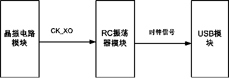
[0034] Such as image 3 , Figure 4As shown, the USB clock generation circuit includes a crystal oscillator circuit module, and the circuit also includes an RC oscillator module that provides a clock signal for the USB module, and the RC oscillator module is connected to the crystal oscillator circuit module and receives the crystal oscillator circuit module The reference clock CK_XO provided; the RC oscillator module includes an RCO subcircuit, a synchronous pulse generation subcircu...
PUM
 Abstract
Description
Claims
Application Information