Oil conservator for sleeve and processing technology of oil conservator

A technology of oil conservator and bushing, which is applied in the direction of electrical components, transformer/inductor parts, circuits, etc. It can solve the problems of unsatisfactory sealing performance, inability to observe oil level changes, and poor stability of pressing parts, etc., to ensure that Excellent sealing performance, convenient installation and reasonable structural design

Active Publication Date: 2020-08-28
JIANGSU ZHIDA ELECTRIC
View PDF3 Cites 3 Cited by
  • Summary
  • Abstract
  • Description
  • Claims
  • Application Information

AI Technical Summary

Problems solved by technology

Due to the current development of transformer technology, the update of this type of bushing technology forces all components including quality and service life to be enhanced, especially for such a large oil conservator. Before installation, first check whether the bushing is damaged and whether the fasteners are Clean the dust and dirt on the surface of the casing. The inner cavity of the conductive pipe of the cable structure must be clean. However, the existing oil conservator has a simple structure. When the oil level is too high, it is easy to cause excessive pressure inside the casing and damage Poor stability can easily lead to oil leakage from the casing, the sealing performance cannot meet the requirements, and the oil level is too low, it is impossible to observe the change of the oil level, so the structure of the oil conservator needs to be improved

Method used


Image

  • Oil conservator for sleeve and processing technology of oil conservator
  • Oil conservator for sleeve and processing technology of oil conservator
  • Oil conservator for sleeve and processing technology of oil conservator

Examples


Embodiment Construction

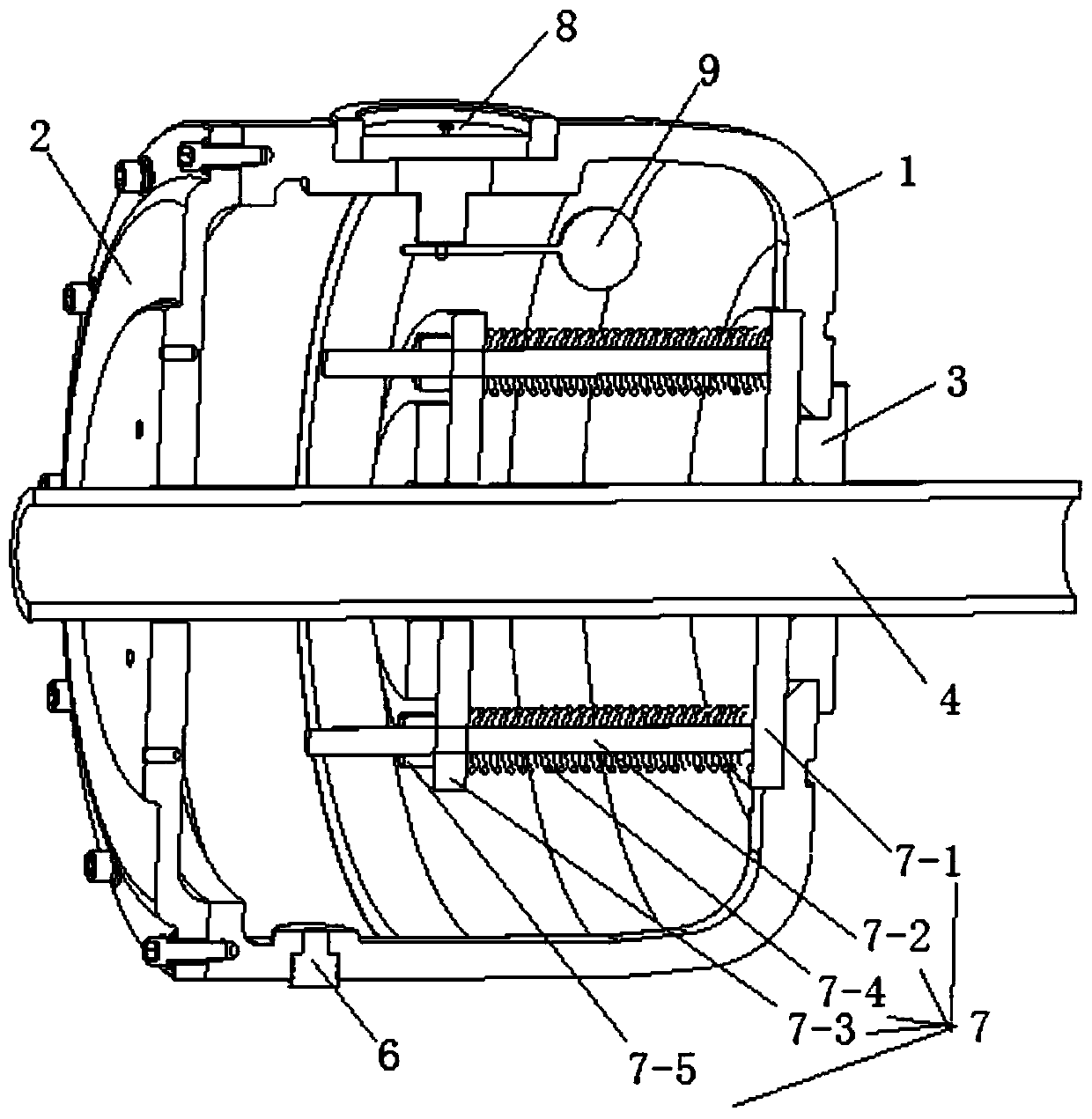
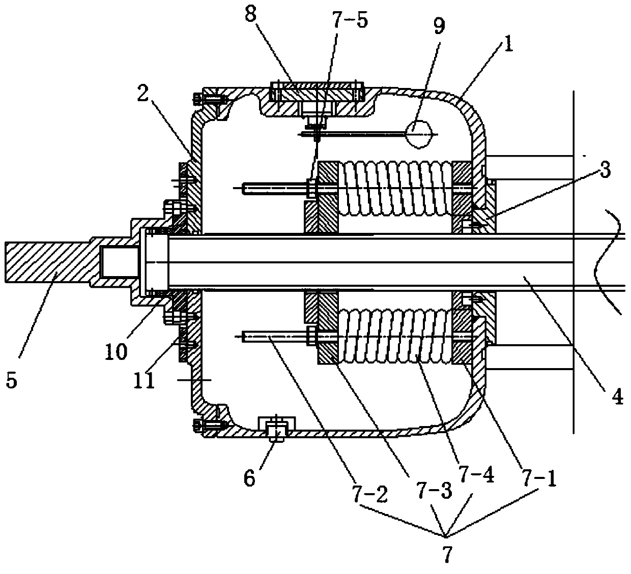
[0024] See attached picture.

[0025] An oil conservator for casing, comprising an oil conservator main body 1, which is a hollow cylindrical structure, an oil conservator cover plate 2 is installed on one end of the oil conservator main body 1, and a rear end is installed on the other end of the oil conservator main body 1 The sealing plate 3, the middle part of the rear end sealing plate 3 and the middle part of the oil conservator cover plate 2 are respectively provided with installation holes, and a copper pipe 4 for conducting electricity is installed in the installation hole, and the front end of the copper pipe 4 protrudes from the end of the oil conservator cover plate 2 In addition, the oil conservator cover plate 2 is equipped with a conductive head 5 matched with the copper pipe, and the rear end of the copper pipe 4 and the oil conservator main body 1 are sealed by the rear end sealing plate 3. A spring compression mechanism 7 for auxiliary pressure sealing is inst...


PUM


Abstract

The invention discloses an oil conservator for a sleeve and a processing technology of the oil conservator. The oil conservator comprises an oil conservator main body, wherein an oil conservator coverplate is mounted at one end of the oil conservator main body, a rear end sealing plate is mounted at the other end of the oil conservator main body, mounting holes are respectively formed in the middle of the rear end sealing plate and the middle of the oil conservator cover plate, a copper pipe for electric conduction is mounted in the mounting hole, the front end part of the copper pipe extendsout of the end of the oil conservator cover plate, a conductive head matched with the copper pipe is mounted on the oil conservator cover plate, the rear end of the copper pipe and the oil conservator main body are pressed and sealed through a rear end sealing plate, a spring pressing mechanism assisting in pressing and sealing is mounted on the copper pipe located in the oil conservator main body, an oil meter is mounted at the upper end of the oil conservator main body, and a connecting rod floating ball extending into the oil conservator main body is mounted at the lower end of the oil meter. According to the invention, a cylindrical transverse and straight placement mode is adopted, detection, oiling and scale discharging can be better facilitated, the rear end sealing plate is pressed and sealed through the counter-acting force of the spring, the sealing performance of the rear end sealing plate is guaranteed, the stability is good, and damage is not likely to happen.

Description

Technical field: [0001] The invention relates to the field of transformers in the electrical industry, and mainly relates to an oil conservator for bushings and a processing technology thereof. Background technique: [0002] The oil conservator is one of the important parts on the bushing. It mainly plays the role of oil storage and can ensure that the oil conservator is full of oil. At the same time, because the contact surface between the oil conservator and the air is reduced, the water and dust absorbed in the air will Oil and grease are deposited on the bottom and can be drained off periodically. There is an oil gauge on the side of the oil conservator, which can detect the change of oil level. Due to the current development of transformer technology, the update of this type of bushing technology forces all components including quality and service life to be enhanced, especially for such a large oil conservator. Before installation, first check whether the bushing is d...

Claims


Application Information

Patent Timeline
Patent Type & Authority Applications(China)
IPC IPC(8): H01F27/02H01F27/14
CPCH01F27/02H01F27/022H01F27/14
Inventor 尹志华
Owner JIANGSU ZHIDA ELECTRIC
Why Eureka
Try Eureka