Light-emitting diode and preparation method thereof
A technology of light-emitting diodes and light-emitting layers, which is applied in semiconductor/solid-state device manufacturing, electrical components, circuits, etc., and can solve problems such as device efficiency drop and efficiency roll-off
- Summary
- Abstract
- Description
- Claims
- Application Information
AI Technical Summary
Problems solved by technology
Method used
Image
Examples
preparation example Construction
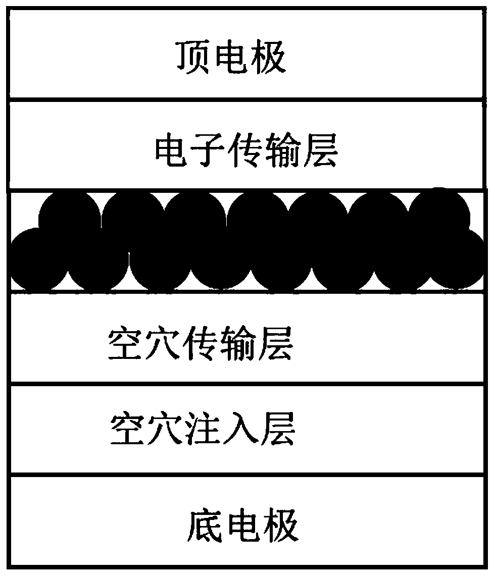
[0047] The present invention also provides a method for preparing a light-emitting diode described in the above technical solution, comprising the following steps:
[0048] After sequentially preparing a hole injection layer, a hole transport layer, a light-emitting layer and an electron transport layer on the upper surface of the bottom electrode, evaporating the top electrode to obtain the light-emitting diode;
[0049] The raw material for the preparation of the luminescent layer is quantum dots with gradient alloy core-shell structure;
[0050] The quantum dots of the gradient alloy core-shell structure have a particle size ≥ 10nm;
[0051] The quantum dots of the gradient alloy core-shell structure are arranged in a gap-filling manner.
[0052] In the present invention, before the hole injection layer is prepared on the upper surface of the bottom electrode, it is also preferred to sequentially clean the bottom electrode and perform ultraviolet-ozone treatment, and the t...
Embodiment 1
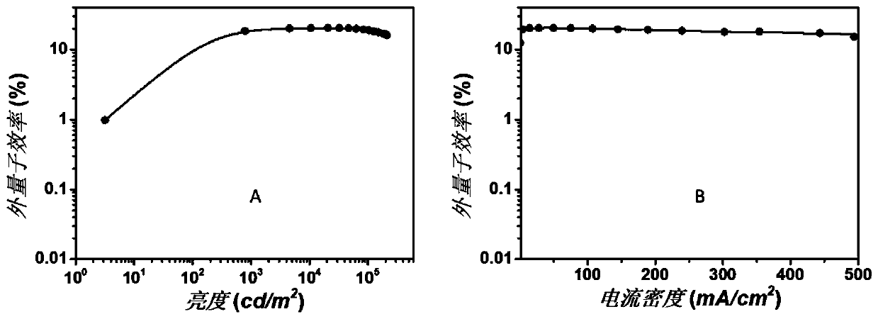
[0057] After the ITO glass substrate was cleaned and treated with UV-ozone (15min) in sequence, the upper surface of the ITO glass substrate was spin-coated (rotating at 2000 rpm) with 35nm thick poly(3,4-ethylenedioxythiophene ): after polystyrene sulfonate is used as the hole injection layer, dry (150° C., 15 min); continue to spin-coat (rotating speed is 3000 rpm) 20nm thick poly[( 9,9-dioctylfluorene-2,7-diyl)-co-(4,4'-(N-(4-sec-butylphenyl)diphenylamine)] as the hole transport layer, dried ( 150° C., 15 min); on the upper surface of the hole transport layer, spin-coat (rotating speed is 2500 rpm) 15 nm thick CdSe / Zn x Cd 1-x Se / ZnSe y S 1-y After / ZnS (diameter is 15nm) as luminous layer (1 layer), dry (60 ℃, 15min); On the upper surface of described luminescent layer, spin-coat (rotating speed is 3000 rpm) 50nm thick zinc oxide as electron transport layer, on the upper surface of the electron transport layer with Evaporate 100nm-thick Al as the top electrode at a s...
Embodiment 2
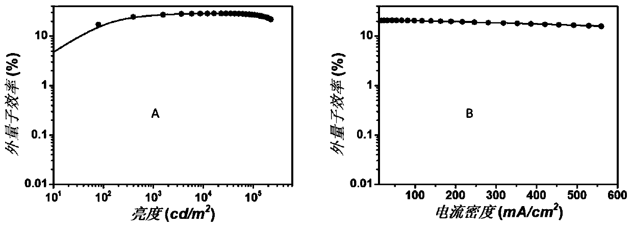
[0060] After the ITO glass substrate was cleaned and treated with UV-ozone (15min) in sequence, the upper surface of the ITO glass substrate was spin-coated (3000 rpm) with 40nm thick polystyrene sulfonate (PEDOT:PSS) After being used as a hole injection layer, dry (150°C, 15min); continue to spin-coat (3000 rpm) 20nm-thick poly[(9,9-dioctylfluorene) on the upper surface of the hole injection layer -2,7-diyl)-co-(4,4'-(N-(4-sec-butylphenyl)diphenylamine)] as the hole transport layer, dried (150°C, 15min); The upper surface of the hole transport layer is spin-coated (rotating speed is 2500 rev / min) 18nm thick Zn x Cd 1-x Se / ZnSe y S 1-y (diameter is 18nm) after being used as luminous layer (1 layer), dry (60 ℃, 15min); After the upper surface of described luminescent layer is spin-coated (rotating speed is 3000 rpm) 50nm thick zinc oxide is used as electron transport layer , on the upper surface of the electron transport layer with Evaporate 100nm-thick Al as the top elec...
PUM
| Property | Measurement | Unit |
|---|---|---|
| particle diameter | aaaaa | aaaaa |
| thickness | aaaaa | aaaaa |
| thickness | aaaaa | aaaaa |
Abstract
Description
Claims
Application Information
 - R&D
- Intellectual Property
- Life Sciences
- Materials
- Tech Scout
- Unparalleled Data Quality
- Higher Quality Content
- 60% Fewer Hallucinations
Browse by: Latest US Patents, China's latest patents, Technical Efficacy Thesaurus, Application Domain, Technology Topic, Popular Technical Reports.
© 2025 PatSnap. All rights reserved.Legal|Privacy policy|Modern Slavery Act Transparency Statement|Sitemap|About US| Contact US: help@patsnap.com


