Rotor structure of permanent magnet synchronous motor

A permanent magnet synchronous motor, rotor structure technology, applied in the magnetic circuit shape/style/structure, engine lubrication, magnetic circuit rotating parts and other directions, can solve the problems of reducing the service life of the rotor, consuming a lot of time, and burning the rotor. , to achieve the effect of prolonging the service life, reducing the working intensity and good lubrication

Active Publication Date: 2020-08-28
威鹏双携(福建龙岩)科技有限公司
View PDF7 Cites 3 Cited by
  • Summary
  • Abstract
  • Description
  • Claims
  • Application Information

AI Technical Summary

Problems solved by technology

[0003] After the existing permanent magnet motor is used for a long time, the shaft will be relatively dry, and it is difficult to lubricate. The motor needs to be disassembled and lubricated, which greatly improves the work intensity of the staff and consumes a lot of time. Moreover, the motor If used for a long time, the permanent magnets of the rotor will generate a lot of heat. If the temperature is too high, it will easily burn out the rotor, thus reducing the service life of the rotor.

Method used


Image

  • Rotor structure of permanent magnet synchronous motor
  • Rotor structure of permanent magnet synchronous motor
  • Rotor structure of permanent magnet synchronous motor

Examples


Embodiment Construction

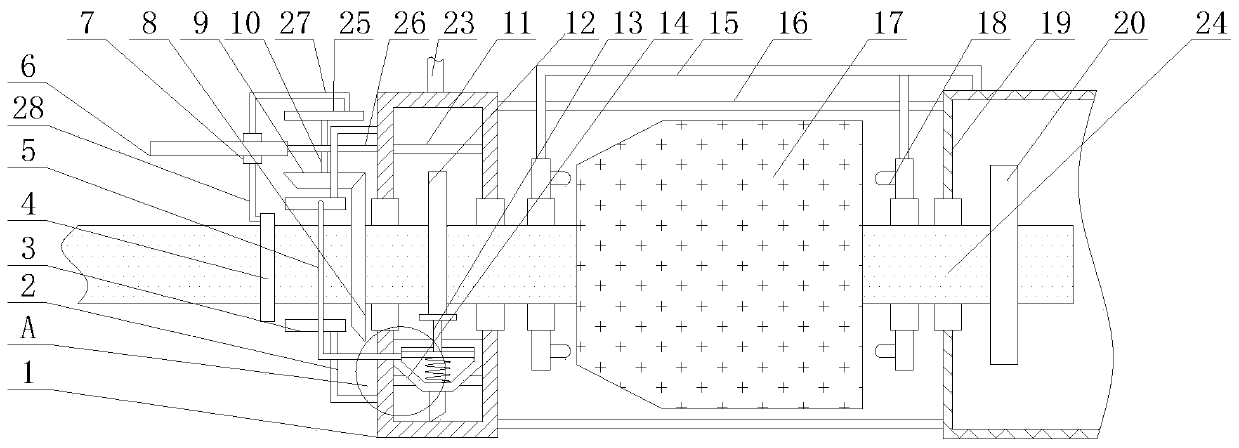
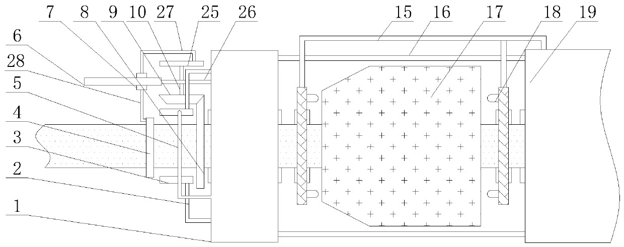
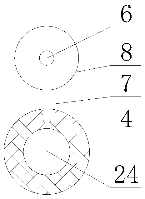
[0027] In order to make the purpose, features and advantages of the present invention more obvious and understandable, the technical solutions in the embodiments of the present invention will be clearly and completely described below in conjunction with the accompanying drawings in the embodiments of the present invention. Obviously, the following The described embodiments are only some, not all, embodiments of the present invention. Based on the embodiments of the present invention, all other embodiments obtained by persons of ordinary skill in the art without making creative efforts belong to the protection scope of the present invention.

[0028] The technical solutions of the present invention will be further described below in conjunction with the accompanying drawings and through specific implementation methods.

[0029] In the description of the present invention, it should be understood that the orientations or positional relationships indicated by the terms "upper", "...


PUM


Abstract

The invention discloses a rotor structure of a permanent magnet synchronous motor. The device comprises an annular cylinder, fixing rods, oil spraying heads, annular sponge blocks, oil guide pipes, sliding groove seats, sliding blocks, bevel gears, bevel pinions, rotating rods, annular partition plates, cams, piston rods, oil collecting funnels, exhaust pipes, connecting rods, permanent magnets, annular air spraying pipes, air boxes, turbines, suction pipes, springs, oil inlet pipes, rotating shafts, rotating discs, transverse plates, sliding rods and supporting rods. Through mutual cooperation of the cam, the suction pipe, the oil collecting funnel, the piston rod and the oil spraying head, lubricating oil can be better lubricated, manual disassembly for lubrication is avoided, the working intensity of workers is greatly reduced, Meanwhile, a large amount of time is also shortened; and through mutual cooperation of the sliding groove seats, the sliding blocks, the annular rubber blocks, the bevel gears and the sliding rods, lubricating oil can be better and evenly wiped, the surface of the rotating shaft is evenly coated with the lubricating oil, and the lubricating efficiency ofthe rotating shaft is greatly improved.

Description

technical field [0001] The invention relates to a rotor structure, in particular to a rotor structure of a permanent magnet synchronous motor, belonging to the technical field of permanent magnet synchronous motors. Background technique [0002] Permanent magnet motors have the advantages of high efficiency, high power factor, and large speed range. Therefore, in high-speed applications, permanent magnet motors are favored. Compared with external permanent magnet rotor motors, inner rotor permanent magnet motors have small rotor radius and strong reliability. Advantages, become the first choice for high-speed motors, and the rotor of the motor is a vital part of the permanent magnet motor. [0003] After the existing permanent magnet motor is used for a long time, the shaft will be relatively dry, and it is difficult to lubricate. The motor needs to be disassembled and lubricated, which greatly improves the work intensity of the staff and consumes a lot of time. Moreover, th...

Claims


Application Information

Patent Timeline
Patent Type & Authority Applications(China)
IPC IPC(8): H02K1/27H02K1/32H02K5/16H02K9/04F16N9/02
CPCH02K1/2706H02K9/04H02K1/32H02K5/16F16N9/02F16N2210/18
Inventor 闵庭辉蔡振凯吴东龙闵庭祥金范洙曾宪威张凌陈保会
Owner 威鹏双携(福建龙岩)科技有限公司
Why Eureka
Try Eureka