Supercharge Your Innovation With Domain-Expert AI Agents!

Linear actuator with smooth clutching

A linear actuator, smooth technology, applied in clutches, mechanically driven clutches, intermeshing clutches, etc., can solve problems such as poor operating experience, damaged clutch devices, and unsmooth clutch devices

Pending Publication Date: 2020-08-28
ZHEJIANG JIECHANG LINEAR MOTION TECH
View PDF0 Cites 2 Cited by
  • Summary
  • Abstract
  • Description
  • Claims
  • Application Information

AI Technical Summary

Problems solved by technology

[0004] For the clutch device, most of the two parts are moved axially by moving one of the two parts to realize the motor docking, and if the two parts are subjected to axial force, it will inevitably affect the difficulty of the shifting, thus The clutch device is not smooth, the operating experience is not good, and the clutch device may even be damaged

Method used


Image

  • Linear actuator with smooth clutching
  • Linear actuator with smooth clutching
  • Linear actuator with smooth clutching

Examples


Embodiment 1

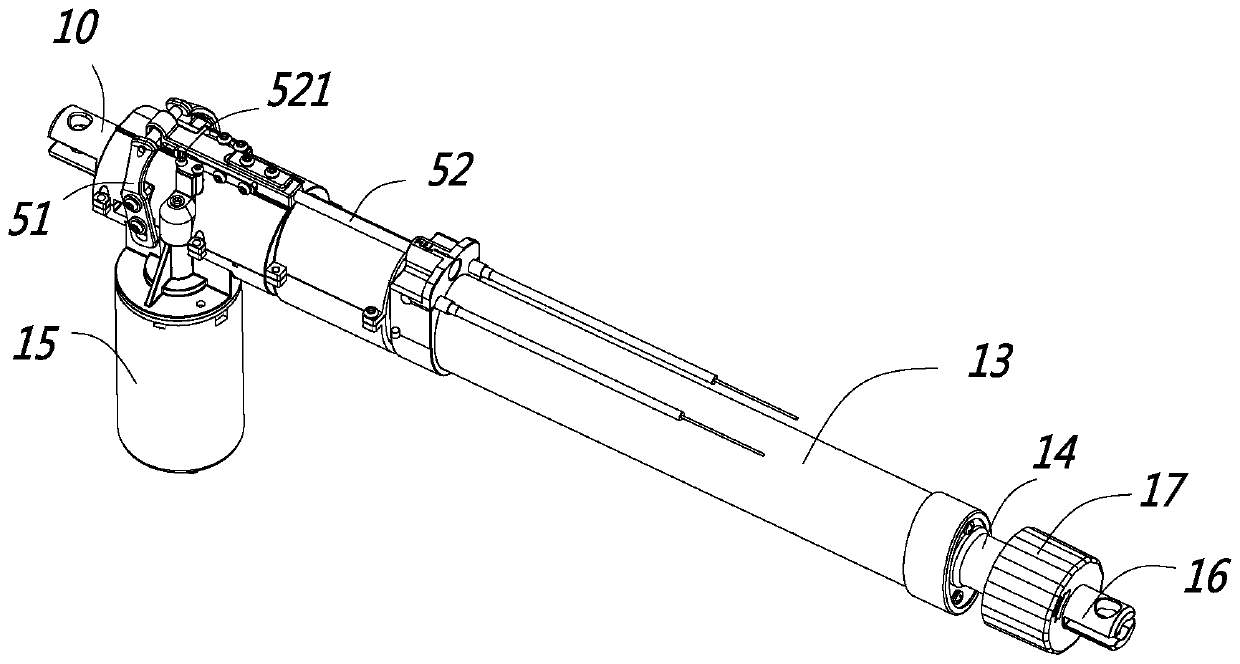
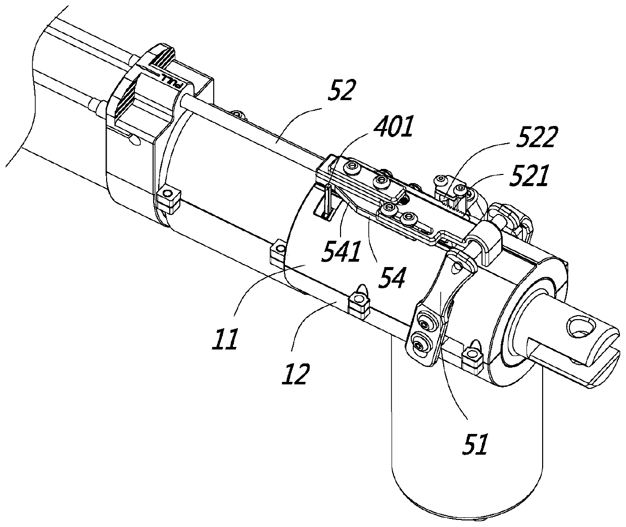
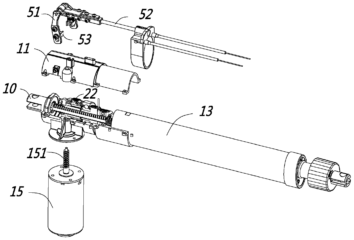
[0036] Such as Figure 1 to Figure 7 As shown, this embodiment is a linear actuator, which is also commonly called a linear actuator or an electric push rod. The linear actuator includes a housing, an outer tube 13, an inner tube 14, a driving motor 15, a transmission assembly, Turn the screw rod 20 and the transmission nut 21, the drive motor 15 drives the rotation screw rod 20 to rotate through the transmission assembly, the rotation of the rotation screw rod 20 drives the transmission nut 21 to move axially along the rotation screw rod 20, and the transmission nut 21 is fixed to the inner tube 14 connected, when the drive nut 21 moves axially, it drives the inner tube 14 to move axially relative to the outer tube 13 and the outer shell, and the outer end of the inner tube 14 is connected to the target to be driven. The linear actuator in this embodiment also include:

[0037] The clutch device is arranged between the transmission assembly and the rotating screw mandrel 20,...

Embodiment 2

[0062] Such as Figure 8 to Figure 11 As shown, the general operation principle of the present embodiment is similar to that of the first embodiment, except that there are differences in the specific structures of the self-locking device, the clutch device, the first driving member, and the second driving member.

[0063] The self-locking device of this embodiment: in the first embodiment, the first friction sleeve 41 and the second friction sleeve 42 are arranged side by side in the axial direction, and the outer end faces of the first friction sleeve 41 and the second friction sleeve 42 are opposed, while in this embodiment In an example, the second friction sleeve 42 is set outside the first friction sleeve 41, and the outer end surface of the first friction sleeve 41 is in contact with the inner end surface of the second friction sleeve 42. For the first friction sleeve 41 and the rotating screw The installation between 20 is the same as the first embodiment, the first frict...


PUM


Abstract

The invention discloses a linear actuator with smooth clutching, and belongs to the technical field of linear transmission. The linear actuator comprises a shell, a transmission worm wheel, a rotatinglead screw and a transmission nut, wherein the transmission worm wheel drives the rotating lead screw to rotate, the rotating lead screw rotates to drive the transmission nut to move in the axial direction of the rotating lead screw, a clutch device is arranged between the transmission worm wheel and the rotating lead screw, the clutch device comprises a coupling gear sleeve capable of axially moving relative to the rotating worm wheel, an axial limiting sleeve piece is sleeved outside the rotating lead screw, the axial limiting sleeve piece abuts against the shell in the axial direction, theaxial limiting sleeve piece and the rotating lead screw are kept positioned in the axial direction, when the rotating lead screw bears axial loads, the rotating lead screw transmits axial force to the shell through the axial limiting sleeve piece, and no axial force is transmitted between the coupling gear sleeve and the axial limiting sleeve piece in the axial direction. The linear actuator hasthe advantage that the smoothness is good when the clutch device is driven.

Description

【Technical field】 [0001] The invention relates to a linear actuator with smooth clutch and belongs to the technical field of linear transmission. 【Background technique】 [0002] Linear actuators, also known as electric push rods, are widely used in furniture, medical equipment, solar power generation, etc. The main structure includes a drive motor, a drive worm, a worm wheel, a screw, and a nut. The working principle is that the drive motor drives the drive worm Rotation, the transmission worm meshes with the worm wheel to drive the worm wheel to rotate, the worm wheel to drive the screw to rotate, the screw to rotate to drive the nut to move axially, the nut is generally connected to the inner tube, so as to realize the telescopic movement of the inner tube. [0003] Combined with the application environment of the linear actuator, when the linear actuator encounters a drive motor failure, or a power failure, or other situations where power needs to be cut off, a clutch dev...

Claims


Application Information

Patent Timeline
Patent Type & Authority Applications(China)
IPC IPC(8): H02K7/116H02K7/06H02K7/108F16D11/14
CPCH02K7/1166H02K7/06H02K7/108F16D11/14F16H2025/209F16H2025/2084F16H2025/2071F16H25/2454F16H25/20F16H2025/2031F16H2025/2463
Inventor 许欣赵新星
Owner ZHEJIANG JIECHANG LINEAR MOTION TECH
Features
  • R&D
  • Intellectual Property
  • Life Sciences
  • Materials
  • Tech Scout
  • Unparalleled Data Quality
  • Higher Quality Content
  • 60% Fewer Hallucinations
Learn More