
Motor control system

A technology of motor control and button control, applied in control systems, motor generator control, AC motor direction control, etc., can solve problems such as single product function and lack of perfect control system system

Inactive Publication Date: 2020-08-28
深圳市康进医疗科技有限公司
View PDF0 Cites 0 Cited by
  • Summary
  • Abstract
  • Description
  • Claims
  • Application Information

AI Technical Summary

Problems solved by technology

[0002] At present, most motor control systems use a single product function to develop new control functions, and there is no perfect control system system

Method used


Image

  • Motor control system
  • Motor control system
  • Motor control system

Examples


Embodiment 1

[0029] Example 1: Please refer to Figure 1-13 In the embodiment of the present invention, resistors R1 to R14, varistors RV, capacitors C1 to C6, rectifier diodes D1 to D4, Zener diode ZD, bidirectional trigger diode DIAC, transistors Q1, Q2, high voltage package T1, optocoupler U1, relay JD and ignition needle / flame needle IG. In this circuit, relay JD, resistor R2, diodes D1, D2, capacitor C5, bidirectional trigger diode DIAC, varistor RV, high-voltage package T1 constitute the pulse ignition circuit, and the other parts constitute the flame detection circuit.

[0030] Such as figure 1 As shown, in this circuit, resistor R1 is connected to one end of resistor R2 and the N pole of the 220V AC power supply neutral line,

[0031] The voltage detection circuit converts the input voltage of the external power supply into the voltage that needs to be applied to the system module. The current system mainly consists of three types of voltage

[0032] 1: External voltage (12-24V). Syst...

Embodiment 2

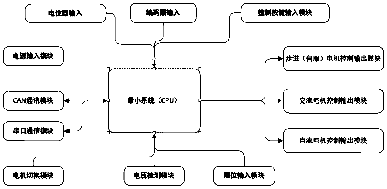
[0047] Embodiment 2: On the basis of Embodiment 1, the minimum CPU system adopts a single-chip microcomputer with the highest frequency of 72MHz, which can quickly process the collected data and communicate with the server. The internal integrated 12-bit AD converter can ensure the accuracy of voltage acquisition. The internal timer is responsible for collecting the pulse value of the encoder. The collected data realizes the requirements of different distances or angles through internal algorithms. Realize the forward and reverse rotation of the motor through key input or communication protocol input. The movement of the motor drives the potentiometer or encoder for movement acquisition.


PUM


Abstract

The invention discloses a motor control system. The controller comprises a voltage detection circuit, a control key input circuit, a limiting input module, a motor switching module, a serial port communication module, a CAN communication module, a direct current motor control output module, a stepping motor control output module, an alternating current motor control output module and a CPU minimumsystem. The device has the functions of voltage detection, limit switch detection, motor control module switching control, encoder data collection and the like; potentiometer motion data collection (can be selected by setting), different motor control modules, CAN communication control modules and serial port communication control modules are provided. The system realizes the development functions of a motor one-to-one motor control system and a one-to-two motor control system. Meanwhile, the application requirements that different motor control systems form different products can be met through the CAN.

Description

Technical field [0001] The invention relates to the technical field of motors, in particular to a motor control system. Background technique [0002] At present, most motor control systems develop new control functions through a single product function, and there is no complete control system system. [0003] The existing system integrates the types of control products that the motor needs to use in the work, organizes all the parameter information of the motor in operation, and can observe the stability of the entire control system in real time. At the same time, the whole system can realize the functions of different motors without secondary development, and only needs the serial port or Can to set the motor operating parameters. Summary of the invention [0004] The purpose of the present invention is to provide a motor control system to solve the problems raised in the background art. [0005] In order to achieve the above objectives, the present invention provides the following...

Claims


Application Information

Patent Timeline
Patent Type & Authority Applications(China)
IPC IPC(8): H02P8/18H02P23/24H02P23/14H02P7/03
CPCH02P7/03H02P8/18H02P23/14H02P23/24
Inventor 匡进姜精水石国雍
Owner 深圳市康进医疗科技有限公司
Learn More