Stirring type cooking utensil
A cooking utensil and stirring technology, which is applied to the field of stirring cooking utensils, can solve the problems of non-centre noise vibration, instability, and large shaking of the container and cup of the knife assembly.
- Summary
- Abstract
- Description
- Claims
- Application Information
AI Technical Summary
Problems solved by technology
Method used
Image
Examples
Embodiment 1
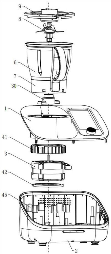
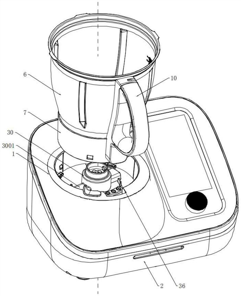
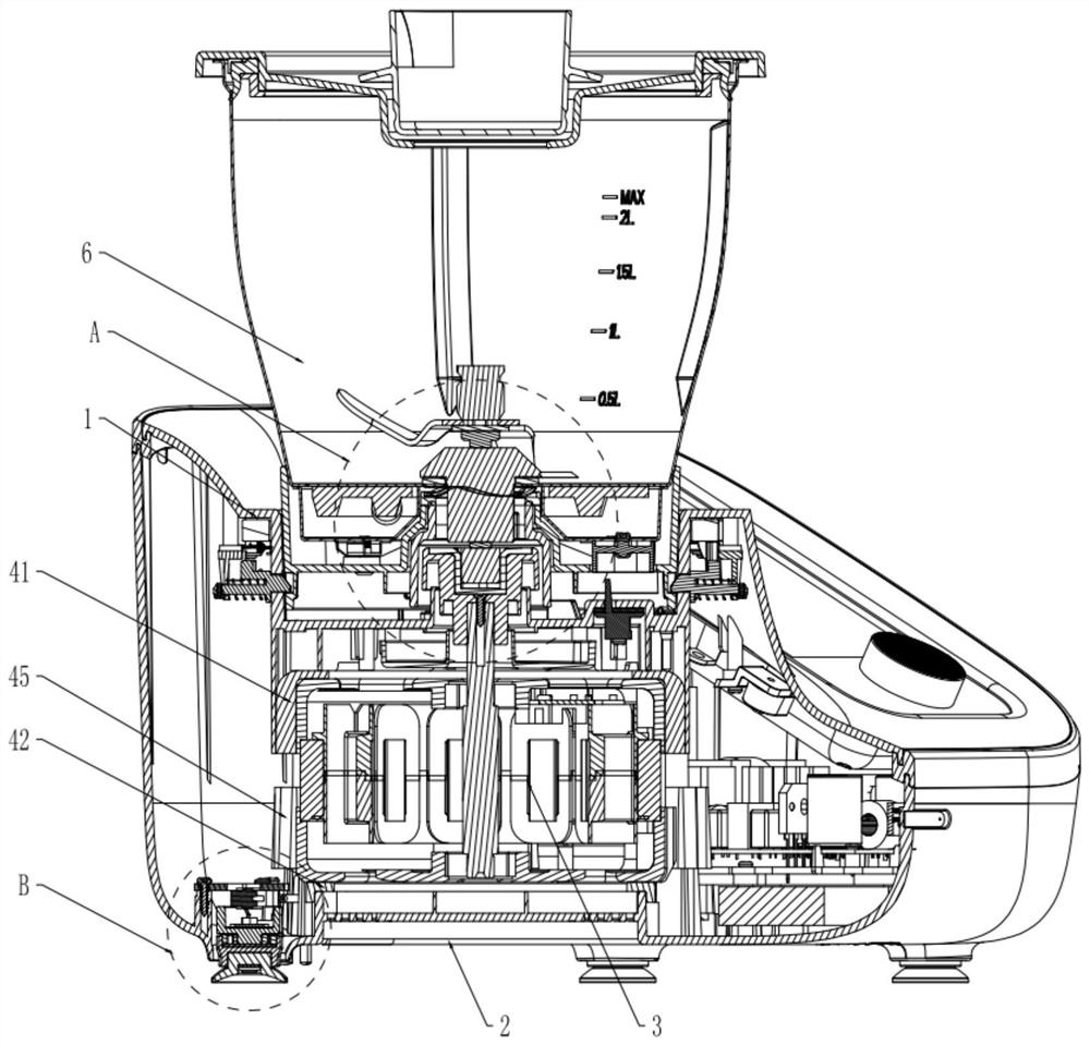
[0120] The present invention relates to the field of cooking utensils. Taking a cooking machine product as an example, a stirring cooking utensil includes a main body casing, a motor 3 assembled in the main body casing, and a container cup assembly 4 detachably assembled on the main body casing. The host housing includes an integrally installed host upper cover 1 and a host base 2, each corner of the host base 2 is provided with a mounting position, and the container cup assembly 4 is interlocked with the host housing through a container cup fixing structure. Unlocking, the container cup assembly 4 and the motor 3 are linked with each other through the cover opening protection structure, the knife assembly in the container cup assembly 4 and the motor 3 are linked with each other through the knife assembly fixing structure, and the installation position is suspended A weighing foot assembly 5 is installed.
[0121] Working principle: In this technical solution, the container c...
Embodiment 2
[0126] Embodiment 2 of the present invention is further improved on the basis of Embodiment 1, so as to fully exert the technical advantages of the present invention, which will be illustrated below.
[0127] For example: if Figure 9-12 As shown, the container cup fixing structure includes a locking part 11, a locking opening 12, a rotating ring 13, a fixing hole 16 and a tension spring 17;
[0128] Among them: the lock parts 11, the number of which is at least three, which are evenly distributed on the periphery of the side wall 101 of the upper cover, which includes a lock bracket 1101, a lock that can be extended / retracted on the lock bracket 1101 , the lock bracket 1101 is fixed on the upper cover outer edge 103 on the periphery of the upper cover side wall 101, the plane where the lock bracket 1101 is located is tangent to the outer edge of the upper cover, and the central axis of the lock bracket 1101 is in line with the lock The central axis of the buckle is perpendic...
Embodiment 3
[0144] Embodiment 3 of the present invention is further improved on the basis of Embodiment 1 / 2, so as to fully exert the technical advantages of the present invention, which will be illustrated below.
[0145] For example: if Figure 13-15 , 28, the cover opening protection structure includes a handle safety link 21, a second return spring 22, a hook buckle 23 and a micro switch 24;
[0146] Among them: the handle safety connecting rod 21, which can move up and down in the hollow working groove of the handle seat, which includes a connecting rod main body 2101, a driving slope 2102 and a driving rod 2103 respectively arranged on the upper and lower parts of the connecting rod main body 2101;
[0147] Wherein: the second return spring 22, which is sleeved on the driving rod 2103 and located between the connecting rod body 2101 and the handle seat 1001;
[0148] Wherein: the hook buckle 23, which is fixedly connected to the lower end of the container cover 9, and its lower par...
PUM
 Abstract
Description
Claims
Application Information
 - R&D
- Intellectual Property
- Life Sciences
- Materials
- Tech Scout
- Unparalleled Data Quality
- Higher Quality Content
- 60% Fewer Hallucinations
Browse by: Latest US Patents, China's latest patents, Technical Efficacy Thesaurus, Application Domain, Technology Topic, Popular Technical Reports.
© 2025 PatSnap. All rights reserved.Legal|Privacy policy|Modern Slavery Act Transparency Statement|Sitemap|About US| Contact US: help@patsnap.com


