
Customized ulna prosthesis

A prosthesis, ulna technology, applied in the direction of prosthesis, manufacturing tools, additive manufacturing, etc., can solve the problems of unable to replace the ulna, unable to retain the distal end of the humerus, poor stability, etc., achieve light specific gravity, improve ingrowth, stability good effect

Pending Publication Date: 2020-09-01
BEIJING CHUNLIZHENGDA MEDICAL INSTR
View PDF5 Cites 3 Cited by
  • Summary
  • Abstract
  • Description
  • Claims
  • Application Information

AI Technical Summary

Problems solved by technology

[0003] However, there is no ulnar tumor prosthesis in the existing technology, and there are the following defects: (1) the existing ulnar prostheses are all elbow joint prostheses. For ulnar tumors, the distal humerus cannot be preserved, that is, a simple ulnar prosthesis cannot be achieved. Replacement; (2) The existing elbow prosthesis relies on bone cement to fix the medullary pin, which has poor medium and long-term stability and is easy to loosen

Method used


Image

  • Customized ulna prosthesis
  • Customized ulna prosthesis

Examples


Embodiment 1

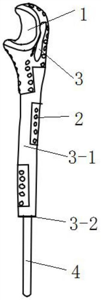
[0028] Please refer to the attached Figure 1-2 , The purpose of this embodiment is to provide a customized ulnar prosthesis, including: a prosthesis body, the material of which is titanium alloy, which has the characteristics of high strength and light specific gravity. The upper end of the prosthesis body is provided with an olecranon groove 1, and the olecranon groove 1 is polished to make the joint surface of the ulnar prosthesis smooth, reduce the wear of the ulnar prosthesis and the human elbow joint surface, and prolong the service life of the prosthesis. The lower end of the prosthesis body is provided with a medullary needle 4, and the medullary needle 4 is a bionic type of medullary needle; the surface of the medullary needle 4 is sprayed, and the surface of the medullary needle 4 has a titanium coating and a hydroxyapatite coating. and tantalum coating; the surface of the sprayed needle 4 is a rough surface with holes, and the holes are preferably micropores. Biomi...

Embodiment 2

[0033] Please refer to the attached Figure 1-2 , The purpose of this embodiment is to provide a customized ulna prosthesis, including: a prosthesis body, the material of the prosthesis body is titanium alloy, which has the characteristics of high strength and light specific gravity. The upper end of the prosthesis body is provided with an olecranon groove 1, and the olecranon groove 1 is polished to make the joint surface of the ulnar prosthesis smooth, reduce the wear of the ulnar prosthesis and the human elbow joint surface, and prolong the service life of the prosthesis. The lower end of the prosthesis body is provided with a medullary needle 4, and the medullary needle 4 is a bionic type of medullary needle; the surface of the medullary needle 4 is sprayed, and the surface of the medullary needle 4 has a titanium coating and a hydroxyapatite coating. and tantalum coating; the surface of the sprayed needle 4 is a rough surface with holes, and the holes are preferably micro...


PUM

PropertyMeasurementUnit
Diameteraaaaaaaaaa
Apertureaaaaaaaaaa
Thicknessaaaaaaaaaa

Abstract

The invention relates to the technical field of medical instruments, and provides a customized ulna prosthesis, which comprises a prosthesis body, an olecranon groove is formed in the upper end of theprosthesis body, and a broach is arranged at the lower end of the prosthesis body; the prosthesis body is further provided with a plurality of suture holes determined according to human ligament attachment points, wherein the suture holes are located between the olecranon groove and the broach; and bone trabecula structures are unevenly arranged in a non-suture-hole area on the surface of the prosthesis body. The ulna prosthesis has the beneficial effects that the articular surface of the ulna prosthesis is smooth, and particularly the olecranon groove is polished, so that the abrasion between the ulna prosthesis and the elbow articular surface of a human body is reduced, and the service life of the prosthesis is prolonged; the plurality of suture holes in the ulna prosthesis act together, so that the early-stage stability of the ulna prosthesis in the human body is guaranteed; and the trabecula structures in the ulna prosthesis can reduce the overall weight of the ulna prosthesis, sothat the bone attachment and bone ingrowth capacity is improved.

Description

technical field [0001] The invention relates to the technical field of medical instruments, and more specifically relates to a customized ulnar prosthesis. Background technique [0002] Prior art Chinese patent application CN110393613A discloses an elbow joint prosthesis. The elbow joint prosthesis includes: a humeral prosthesis, a first lug and a second lug extending away from the length direction of the humeral prosthesis are respectively formed on the opposite sides of the connecting end of the humeral prosthesis, the first lug The ear is provided with a first through hole, and the second lug is provided with a second through hole coaxial with the first through hole; for the ulnar prosthesis, the end of the ulnar prosthesis opposite to the connecting end is provided with a third through hole the rotating shaft assembly, the rotating shaft assembly includes a rotating shaft, and the rotating shaft is used to pass through the first through hole, the second through hole and...

Claims


Application Information

Patent Timeline
IPC IPC(8): A61F2/38
CPCA61F2/3804A61F2/30942A61F2/30771A61F2002/3831A61F2002/30985A61F2310/00023A61F2002/30011A61F2002/30024A61F2002/30784
Inventor 史春宝许奎雪何建民荀世界李明洋康树靖王振国
Owner BEIJING CHUNLIZHENGDA MEDICAL INSTR
Learn More