Method for Modeling Glenoid Anatomy and Optimization of Asymmetric Component Design

a glenoid and component design technology, applied in the direction of shoulder joints, prostheses, applications, etc., can solve the problems of individual patient specific location and length of fixation sites, and achieve the effect of optimizing the fixation site length and specific location

Pending Publication Date: 2022-10-27
MAYO FOUND FOR MEDICAL EDUCATION & RES
View PDF0 Cites 0 Cited by
  • Summary
  • Abstract
  • Description
  • Claims
  • Application Information

AI Technical Summary

Problems solved by technology

In addition, the specific location and length of the f

Method used


Image

  • Method for Modeling Glenoid Anatomy and Optimization of Asymmetric Component Design
  • Method for Modeling Glenoid Anatomy and Optimization of Asymmetric Component Design
  • Method for Modeling Glenoid Anatomy and Optimization of Asymmetric Component Design

Examples


example

[0071]The following Example has been presented in order to further illustrate the invention and is not intended to limit the invention in any way.

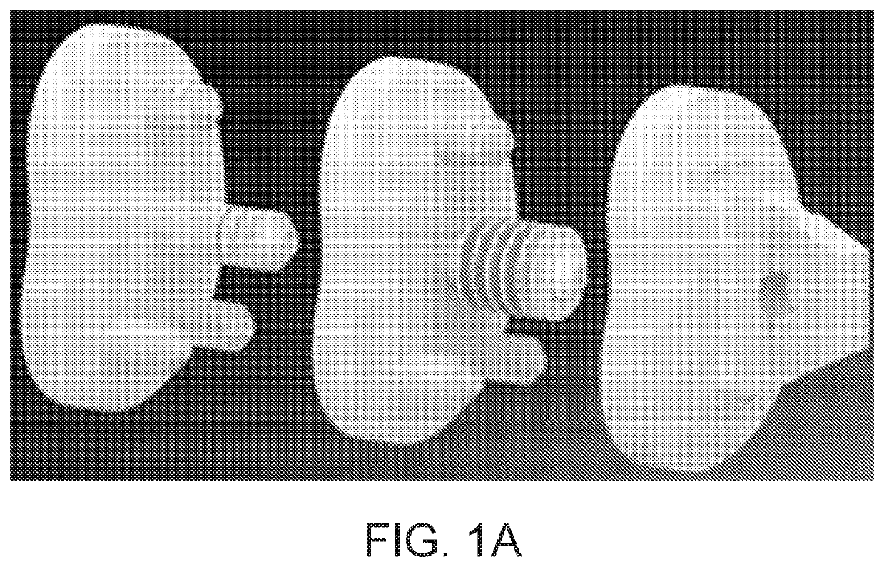
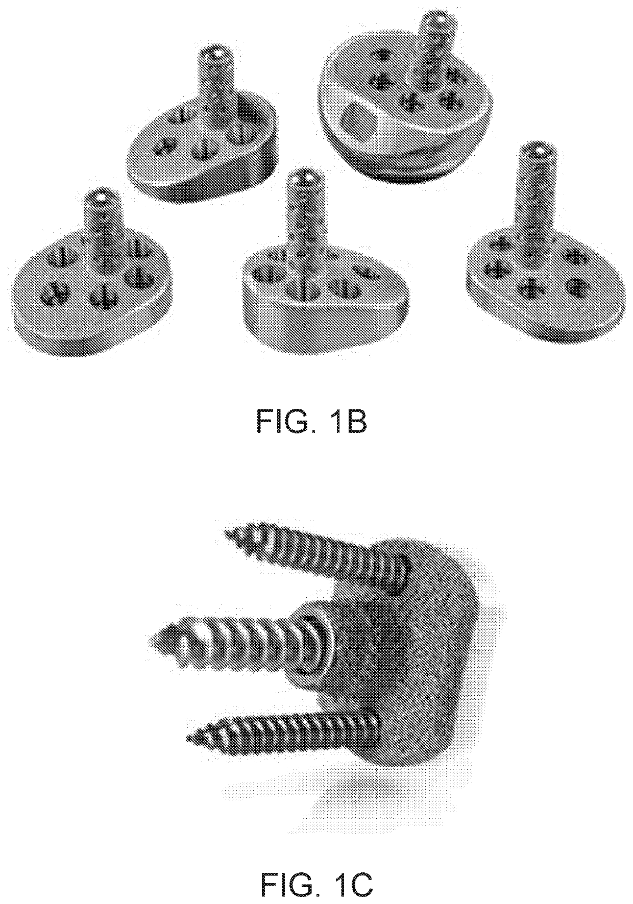
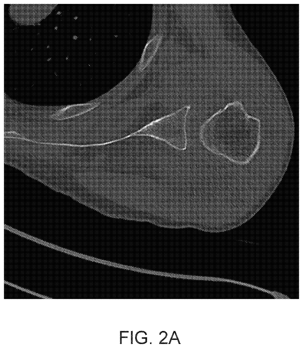
[0072]There has been a drive towards bone preserving and less invasive procedures. However, significant deficiencies have been found in currently available devices that do not optimize fixation. Many of the devices used are round with a uniform shape. This results in greater bone removal to make the patients anatomy fit the implant, rather than the implant being designed to match their anatomy. Excessive bone removal and non-optimized fixation sites can result in increased stress at the device bone interface and concern about early catastrophic loosening. This methodology facilitates designing the shape and size of fixation sites for glenoid fixation that are based on the true anatomy of patients undergoing these procedures. Currently, glenoid fixation sites are not anatomic in size, shape, and relative angular position to the glenoid vaul...


PUM


Abstract

Glenoid components with asymmetric fixation points are provided. Also, methods and devices are provided for the optimization of shoulder arthroplasty component design through the use of medical imaging data, such as computed tomography scan data. The methodology may improve the understanding of glenoid anatomy through the use of medical imaging data and 3D modeling, and for glenoid components that exploit this methodology. The methodology provides for how anatomical features change based on the specific location in the glenoid. The methodology can optimize loading and fit at the bone-device interface. Asymmetrical glenoid components are provided with significantly improved initial fixation.

Description

CROSS-REFERENCE TO RELATED APPLICATIONS[0001]This application claims the benefit of U.S. Provisional Patent Application Ser. No. 62 / 906,237 filed on Sep. 26, 2019 and entitled “Method for Modeling Glenoid Anatomy and Optimization of Asymmetric Component Design,” which is incorporated herein by reference as if set forth in its entirety for all purposes.BACKGROUND OF THE INVENTION1. Field of the Invention[0002]The invention relates to methods for the optimization of joint arthroplasty component design and shoulder arthroplasty components such as glenoid components for joint arthroplasty.2. Description of the Related Art[0003]Various prostheses for the replacement of the shoulder joint are known. In one example shoulder prosthesis, the glenoid is replaced by a glenoid component including a base with a central body as well as protrusions, fins, or pegs that extend from the base into bores formed within the glenoid or holes in the base that allow for screw fixation of the glenoid compone...

Claims


Application Information

Patent Timeline
IPC IPC(8): A61F2/40A61F2/30
CPCA61F2/4081A61F2/30942A61F2002/30784A61F2002/30891A61F2002/30604A61F2002/30878A61F2002/30897A61F2/34A61F2002/30313A61F2002/30894A61F2002/30948A61F2002/30952A61F2002/30985A61F2002/3412A61F2002/3432A61F2002/3446A61F2002/3454A61F2002/4085B33Y80/00
Inventor SPERLING, JOHN W.
Owner MAYO FOUND FOR MEDICAL EDUCATION & RES
Why Eureka
Try Eureka