Vertebral prosthesis

A vertebral body and prosthesis technology, applied in the field of vertebral body prosthesis, can solve the problems of prolapse, thread prolapse, and the unstable coordination between the external thread and the threaded hole, etc., to achieve a good support effect and prevent the effect of sinking

Active Publication Date: 2020-09-01
BEIJING CHUNLIZHENGDA MEDICAL INSTR
View PDF9 Cites 3 Cited by
  • Summary
  • Abstract
  • Description
  • Claims
  • Application Information

AI Technical Summary

Problems solved by technology

In clinical and biomechanical tests, it is found that after a period of use, the cooperation between the above-mentioned external thread and the threaded hole is not stable enough, and the thread is prone to prolapse, which in turn leads to the displacement or even prolapse of the main body of the artificial vertebral body
In addition, the connection between the transverse screw and the main body of the artificial vertebral body is prone to fracture due to the shear force of the screw

Method used


Image

  • Vertebral prosthesis
  • Vertebral prosthesis
  • Vertebral prosthesis

Examples


Embodiment Construction

[0026] Hereinafter, the present invention is described in more detail to facilitate understanding of the present invention.

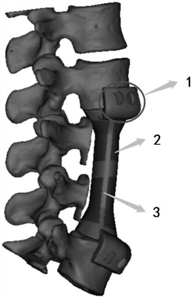
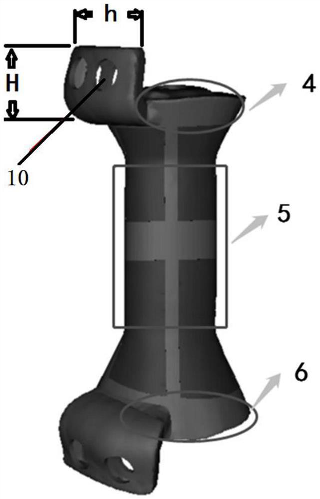
[0027] Such as Figure 1 to Figure 4 As shown, the vertebral body prosthesis of the present invention includes a wing plate 1, a vertebral body upper end 4, a vertebral body middle part 5 and a vertebral body lower end 6, and the vertebral body upper end is directly in contact with the bone surface, and the vertebral body upper end is directly extracted contact with the complete bony surface; the design concept of the lower end of the vertebral body is the same as that of the upper end of the vertebral body, and the lower end of the vertebral body is also directly extracted to contact the complete bony surface; the middle part of the vertebral body is connected between the upper end of the vertebral body and the lower end of the vertebral body Among them, the middle part of the vertebral body includes a trabecular bone structure 2 and a solid structure ...


PUM


Abstract

The invention relates to a vertebral prosthesis, which comprises wing plates, a vertebral body upper end, a vertebral body middle part and a vertebral body lower end. The vertebral body upper end is in direct contact with a bone surface, and the vertebral body upper end directly contacts and extracts the complete bone surface; the vertebral body lower end and the vertebral body upper end have thesame design concept; the vertebral body middle part is connected between the vertebral body upper end and the vertebral body lower end and comprises a bone trabecula structure and a solid structure; the solid structure is formed by printing by directly adopting a 3D printing technology to simulate the original cortical bone of a human body; and the wing plates comprise the upper wing plate and thelower wing plate. The upper wing plate is arranged on the side face of the vertebral body upper end. The lower wing plate is arranged on the side face of the vertebral body lower end; a first nail hole and a second nail hole are formed in the upper wing plate, and the upper wing plate, the first nail hole and the second nail hole form a separation blade structure; and the lower wing plate is alsoprovided with a first nail hole and a second nail hole, and the lower wing plate, the first nail hole and the second nail hole also form a separation blade structure.

Description

technical field [0001] The invention relates to the technical field of medical devices, in particular to a vertebral body prosthesis. Background technique [0002] In the treatment of human spine diseases, vertebral body destruction is often caused by spinal tumors, tuberculosis and severe fractures, which may lead to spinal cord nerve damage and have to perform vertebral body resection. The spine after vertebral body resection needs to rebuild its stability, and the emergence of artificial vertebral body replacement provides an ideal method for the treatment of such diseases. Since the first report of vertebral body tumor resection and prosthetic replacement in the late 1960s, artificial vertebral bodies have been widely used clinically as a kind of effective vertebral body substitutes. [0003] However, in clinical application and a series of biomechanical tests, it has been shown that the traditional artificial vertebra has some problems to be solved in some aspects, esp...

Claims


Application Information

Patent Timeline
Patent Type & Authority Applications(China)
IPC IPC(8): A61F2/44
CPCA61F2/4465A61F2/30771A61F2002/30784
Inventor 许奎雪史春宝王建超原帅康树靖李喜旺荀世界李宁史文超王振国
Owner BEIJING CHUNLIZHENGDA MEDICAL INSTR
Why Eureka
Try Eureka