Feeding and blanking device

A technology of silo and mounting plate, which is applied in the field of loading and unloading devices, can solve the problems of being placed alone at the detection station, and achieve the effect of simple structure and convenient operation

Active Publication Date: 2020-09-01
BOZHON PRECISION IND TECH CO LTD
View PDF10 Cites 4 Cited by
  • Summary
  • Abstract
  • Description
  • Claims
  • Application Information

AI Technical Summary

Problems solved by technology

In order to protect the electronic products from damage during transportation and facilitate transportation, each product will be placed on a pallet for transmission between stations, but during inspection, the product can only be placed on the inspection station alone, so In the loading and unloading process of the loading and unloading device, the problem of the pallet needs to be considered

Method used


Image

  • Feeding and blanking device
  • Feeding and blanking device
  • Feeding and blanking device

Examples


Embodiment 1

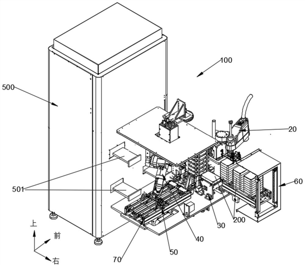
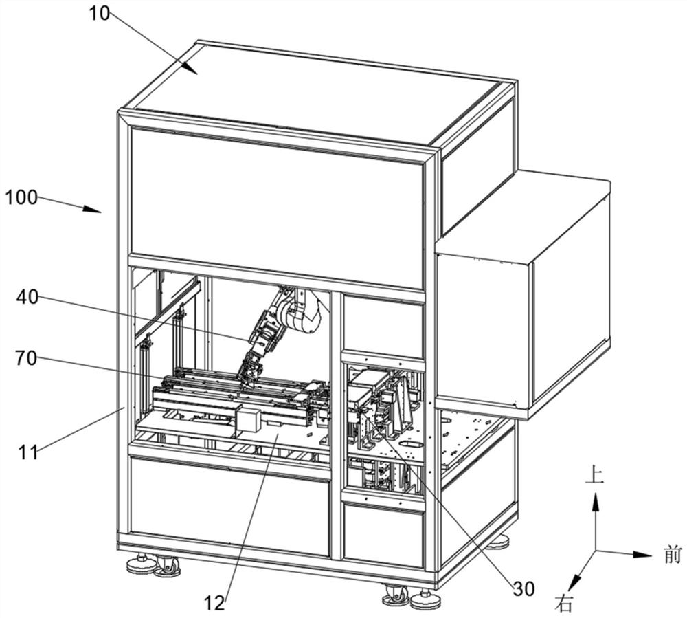
[0084] refer to Figure 1-3 , the present embodiment is to provide a loading and unloading device, which specifically includes a frame 10 and is located on the frame 10:

[0085] The first manipulator 20 is used to take the tray 200 on which the product 400 to be inspected is placed from the feeding device; at the same time, the tray 200 on which the product 400 has been inspected is placed back into the feeding device;

[0086] The bin device 30 is used to store the pallet 200 delivered by the first manipulator 20;

[0087] The second manipulator 40 is used to take out the product 400 to be tested from the pallet 200 of the bin device 30, and place it on the detection station 501 of the detection device 500; at the same time, the product 400 that has been detected is taken out by the detection station 501, Put back in the empty tray of feed bin device 30 again.

[0088] The loading and unloading device 100 provided in this embodiment first moves the product 400 and its tray...

Embodiment 2

[0100] This embodiment is to provide a bin device, which is mainly used in the loading and unloading device 100 provided in the first embodiment, and can put the tested products 400 back into the original tray 200 . Specifically, refer to Figure 4 , the silo device 30 includes:

[0101] The first bin 31 is used to place the tray 200 transported by the first manipulator 20 containing the product 400 to be inspected;

[0102] The second silo 32 is used to store the empty trays delivered by the first silo 31;

[0103] The third silo 33 is used to receive the empty trays delivered by the second silo 32 , and the products 400 that have been tested are put back into the original trays 200 in the third silo 33 .

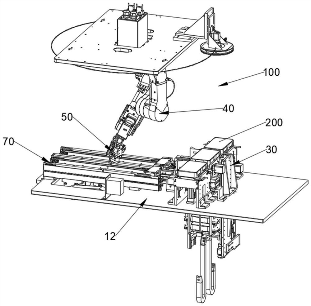
[0104] Further, refer to image 3 with Figure 4 , the first silo 31, the second silo 32 and the third silo 33 are sequentially arranged linearly on the support plate 12, which not only facilitates the transfer of empty pallets between each other, but also compresses t...

Embodiment 3

[0138] For electronic products, due to their fine internal structure, in order to avoid damage caused by shaking during assembly and transportation, the electronic product 400 is usually loaded on the carrier 300, and then the carrier 300 is placed on the pallet 200 as a whole to ensure The product 400 is solid. Specifically, refer to Figure 10 and Figure 11 , a storage slot 304 is provided on the carrier 300, and the product 400 is placed in the storage slot 304; in order to prevent the product 400 from shaking, elastic claws 301 are provided on the side wall of the storage slot 304 to clamp the product 400 horizontally. After the product 400 is manufactured or the corresponding inspection is completed, the carrier 300 will no longer function, and the product 400 does not need to be put back into the carrier 300, but can be placed directly in the tray 200; and the carrier 300 can be collected uniformly for future use. The use of the next batch of products 400 , therefore,...


PUM


Abstract

The invention discloses a feeding and blanking device. The feeding and blanking device comprises a stock bin device, a first manipulator, and a second manipulator. The stock bin device is used for storing trays. The first manipulator is used for conveying the trays where to-be-detected products are placed to the stock bin device and moving the trays where the detected products are placed out of the stock bin device. The second manipulator is used for taking the to-be-detected products out of the trays of the stock bin device, placing the to-be-detected products on detection stations, then taking the detected products out of the detection stations and finally putting the detected products back into the empty trays of the stock bin device. The stock bin device comprises a first stock bin used for placing the trays which are conveyed by the first manipulator and loaded with the to-be-detected products, a second stock bin used for storing the empty trays conveyed by the first stock bin, and a third stock bin is used for receiving the empty trays conveyed by the second stock bin, and the detected products are put back into the original trays in the third stock bin. According to the feeding and blanking device, the trays can be properly placed, and the detected products can be put back into the original trays.

Description

technical field [0001] The invention relates to the technical field of mechanical automation, in particular to a loading and unloading device. Background technique [0002] With the development of mechanical manufacturing in the direction of automation and intelligence, the operation of picking and placing parts of the loading and unloading device has also become complicated. Especially for electronic products, in order to achieve better quality control, it is often necessary to use the loading and unloading device to take out the product to be tested from the feeding device, and place it on the detection station of the detection device to complete the loading; after the detection is completed, It is also necessary to take out the product from the detection station and put it back to the feeding device to complete the blanking. In order to protect the electronic products from damage during transportation and facilitate transportation, each product will be placed on a pallet...

Claims


Application Information

Patent Timeline
Patent Type & Authority Applications(China)
IPC IPC(8): B65G47/52B65G47/90
CPCB65G47/52B65G47/90
Inventor 万发蒋玉斌
Owner BOZHON PRECISION IND TECH CO LTD
Why Eureka
Try Eureka