Ultrasonic lace machine

An ultrasonic and lace machine technology, applied in textile and papermaking, fabric surface trimming, thorn patterns, etc., can solve the problems of inconvenient layout, large space occupied, long transmission path, etc., and achieve convenient layout, short path and installation space. small effect

Pending Publication Date: 2020-09-01
台州通宇服装机械科技有限公司
View PDF1 Cites 0 Cited by
  • Summary
  • Abstract
  • Description
  • Claims
  • Application Information

AI Technical Summary

Problems solved by technology

[0004] In the lace machine of this structure, the flower wheel is movably connected with the transmission shaft through the sprocket and chain, and the input end of the transmission shaft is connected with the transmission motor through the sprocket and chain. The transmission motor is installed at the bottom of the workbench, and the transmission motor occupies external installation space
Moreover, the transmission mechanism composed of sprocket, chain, transmission shaft, etc. occupies the internal space of the machine head. The transmission motor is connected to the transmission shaft through the sprocket and chain, and the transmission shaft is connected to the flower wheel through the sprocket and chain. The transmission path is long. , and runs through the entire machine head, occupying a large space, which affects the layout of other components such as wires, air pipes, etc., and the layout is inconvenient

Method used


Image

  • Ultrasonic lace machine
  • Ultrasonic lace machine
  • Ultrasonic lace machine

Examples


Embodiment 1

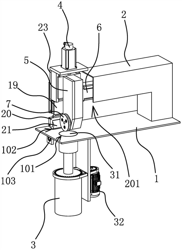
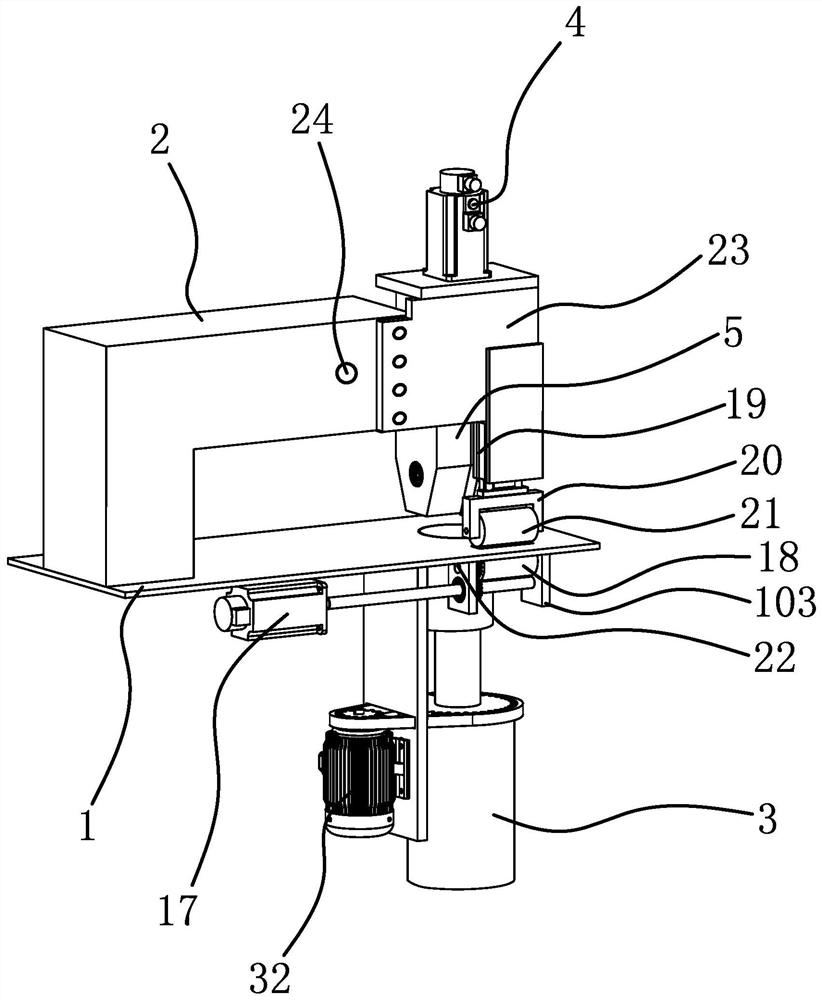
[0033] like figure 1 , figure 2 As shown, the ultrasonic lace machine includes a worktable 1, a machine head 2, an ultrasonic transducer assembly 3, a fifth driving member 32, a first driving member 4, a sliding frame 5, a second driving member 6, a flower wheel 7, a transmission mechanism, The third driving member 17 , the fourth driving member 19 and the mounting plate 23 . In this embodiment, the first driving member 4 and the fourth driving member 19 are driving cylinders, and the second driving member 6, the third driving member 17 and the fifth driving member 32 are servo motors. In actual production, the first driving member 4 and the fourth driving member 19 are driving oil cylinders, and the second driving member 6, the third driving member 17 and the fifth driving member 32 can be rotary cylinders.

[0034] The handpiece 2 is fixed above the workbench 1, the interior of the handpiece 2 has a cavity, the ultrasonic transducer assembly 3 is fixed under the workbench...

Embodiment 2

[0042] The structure and principle of this embodiment are basically the same as those of the first embodiment. The difference is that in this embodiment, the handpiece 2 has a downwardly protruding accommodating cavity, and along the vertical direction, the accommodating cavity is located in the second driving member Right below 6, the second driving member 6 can move down to be located in the accommodating cavity.

Embodiment 3

[0044] The structure and principle of this embodiment are basically the same as those of the first embodiment. The difference is that in this embodiment, the transmission mechanism can be a gear set, and through the cooperation of multiple gears, the second driving member 6 can drive the flower wheel 7 to rotate. .


PUM


Abstract

The invention provides an ultrasonic lace machine, belonging to the technical field of lace machines and solving a problem that the existing lace machine is inconvenient to arrange. The ultrasonic lace machine provided by the invention comprises a workbench, a machine head, an ultrasonic transduction component, a first driving piece and a sliding frame fixedly connected on an output end of the first driving piece, the workbench comprises a penetrating first through hole, a stitching end at a top part of the ultrasonic transduction component is embedded in the first through hole, the first driving piece can drive the sliding frame to move up and down, the top part of the sliding frame is fixedly connected with a second driving piece, and the second driving piece is located in the machine head; a transmission mechanism is arranged in the sliding frame, a bottom part of the sliding frame is provided with a lace wheel, and by the transmission mechanism, the second driving piece can drive the lace wheel to rotate; and the stitching end and the lace wheel interact with each other to realize stitching. The ultrasonic lace machine has the advantages that a driving component driving the lace wheel to rotate occupies small installation space, and the ultrasonic lace machine is convenient to arrange.

Description

technical field [0001] The invention belongs to the technical field of lace machines, and relates to an ultrasonic lace machine. Background technique [0002] Ultrasonic lace sewing machine, also known as ultrasonic lace machine and ultrasonic embossing machine, is an efficient sewing and embossing equipment. It is mainly used for edging, welding, fusion cutting, embossing, etc. of synthetic fiber fabrics. The processed products have good water tightness and high production efficiency. [0003] Existing lace machines, such as Chinese patent documents disclose ultrasonic lace machines with extra-wide tool horns [Application No.: 201120267471.0; Authorization Announcement No.: CN202187217U], which include a workbench, a frame for supporting the workbench, The transducer assembly and ultrasonic generator installed under the worktable, the machine head, drive shaft, hydraulic damping cylinder, and flower wheel installed above the worktable; the transducer assembly includes tran...

Claims


Application Information

Patent Timeline
Patent Type & Authority Applications(China)
IPC IPC(8): D06C23/04
CPCD06C23/04
Inventor 邢增松
Owner 台州通宇服装机械科技有限公司
Why Eureka
Try Eureka