Forming mechanism of paper pulp molding equipment

A pulp molding and forming mechanism technology, applied in textiles and papermaking, etc., can solve the problems of overflow splashing, sedimentation pulp, insufficient pulp volume, etc., and achieve the effect of ensuring product quality and uniform concentration

Pending Publication Date: 2020-09-01
弼伽机械科技无锡有限公司
View PDF0 Cites 1 Cited by
  • Summary
  • Abstract
  • Description
  • Claims
  • Application Information

AI Technical Summary

Problems solved by technology

[0002] Pulp molding is a three-dimensional papermaking technology. It uses waste paper as raw material, and molds a certain shape of paper products with a special mold on the molding machine. During the molding process, the lower mold needs to be placed in the pulp in the pulp tank The lower reciprocating movement is used for pulp suction. After the pulp suction is completed, part of the water is discharged through the pulp suction pipe, so that the pulp stays on the lower forming die. The lower forming die rises and then cooperates with the upper die to shape. During the process, the pulp water in the pulp tank must overflow to the outer cavity before being discharged. The inner cavity of the pulp tank of traditional pulp molding equipment is generally square, and there are dead corners in the inner cavity. During the reciprocating movement of the upper and lower molds , will cause uneven pulp water concentration, insufficient pulp volume, sedimentation, overflow and splashing, etc.

Method used


Image

  • Forming mechanism of paper pulp molding equipment
  • Forming mechanism of paper pulp molding equipment
  • Forming mechanism of paper pulp molding equipment

Examples


Embodiment Construction

[0030] The specific implementation of this embodiment will be described below in conjunction with the accompanying drawings.

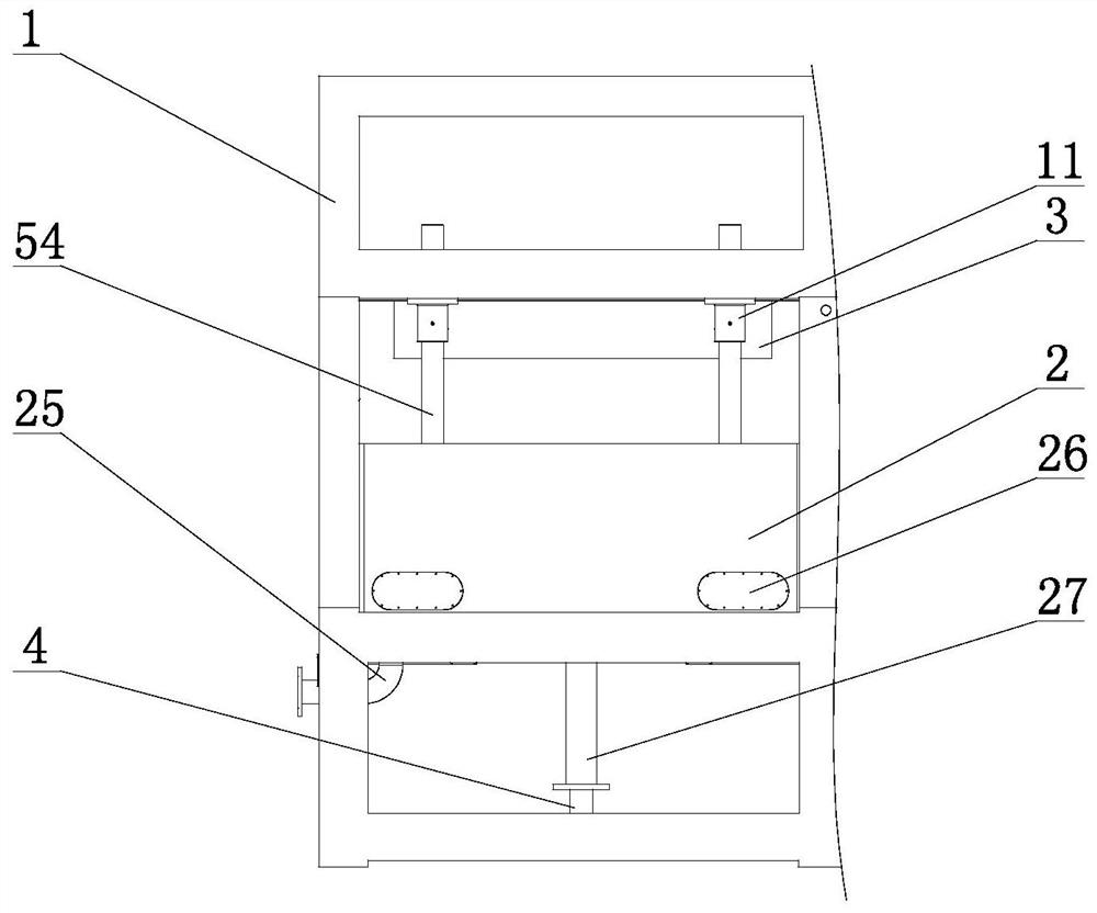
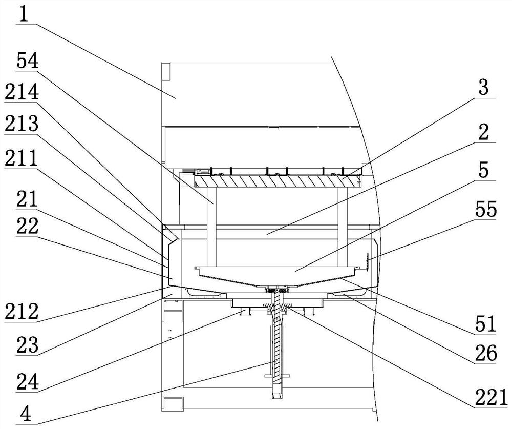
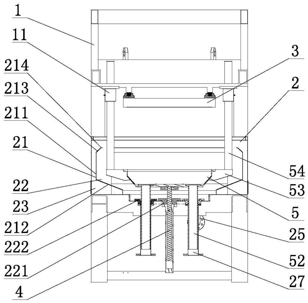
[0031] Such as Figure 1 to Figure 10 As shown, the molding mechanism of the pulp molding equipment of this embodiment includes a frame 1 connected to the pulp tank 2, and the frame 1 is located above the pulp tank 2 and connected to the upper mold 3, and the pulp tank 2 is passed through a partition 21 is divided into an inner chamber 22 and an outer chamber 23, the inner chamber 22 is connected to the slurry inlet pipe 24, the outer chamber 23 is connected to the overflow pipe 25, the partition 21 includes a vertical section 211, and the lower end of the vertical section 211 is connected to a downward slope Section 212, the lower inclined section 212 is inclined towards the central direction of the pulp tank 2, and the partition plate 21 is located at the upper end of the vertical section 211 to connect the upwardly inclined upper inclined section 21...


PUM


Abstract

The invention relates to a forming mechanism of paper pulp molding equipment. The forming mechanismcomprises a machine frame, wherein the machine frame is connected with a paper pulp tank; the machineframe is positioned above the paper pulp tank and is connected with an upper die; the interior of the paper pulp tank is divided into an inner cavity and an outer cavity through a partition plate. The inner cavity is connected with a slurry inlet pipe; the outer cavity is connected with an overflow pipe; the partition plate comprises a vertical section; the lower end of the vertical section is connected with a lower inclined section which is inclined downwards; the lower inclined section inclines towards the center of the paper pulp tank; the machine frame is located on the lower side of theinner cavity of the paper pulp tank and connected with a lifting driving part; the driving end of the lifting driving part extends into the inner cavity of the paper pulp tank and is connected with aforming lower die; the lower side of theforming lower die is provided with a lower inclined surface mathed with the lower incline section of the partition plate; the lower side of the forming lower die is connected with a pulp suction pipe; the pulp suction pipe passes through the paper pulp tank and extend to the lower side of the paper pulp tank. According to the forming mechanism of the paper pulp molding equipment, paper pulp concentration is uniform and sufficient, and nopulp accumulation and overflow splashing is caused.

Description

technical field [0001] The invention relates to a sealing mechanism, in particular to a molding mechanism of pulp molding equipment. Background technique [0002] Pulp molding is a three-dimensional papermaking technology. It uses waste paper as raw material, and molds a certain shape of paper products with a special mold on the molding machine. During the molding process, the lower mold needs to be placed in the pulp in the pulp tank The lower reciprocating movement is used for pulp suction. After the pulp suction is completed, part of the water is discharged through the pulp suction pipe, so that the pulp stays on the lower forming die. The lower forming die rises and then cooperates with the upper die to shape. During the process, the pulp water in the pulp tank must overflow to the outer cavity before being discharged. The inner cavity of the pulp tank of traditional pulp molding equipment is generally square, and there are dead corners in the inner cavity. During the re...

Claims


Application Information

Patent Timeline
Patent Type & Authority Applications(China)
IPC IPC(8): D21J5/00
CPCD21J5/00
Inventor 郑武明陈炳光
Owner 弼伽机械科技无锡有限公司
Why Eureka
Try Eureka