Pulping assembly of pulping pump

A technology of pulping and components, applied in the direction of pump components, pumps, pumping devices for elastic fluids, etc., can solve problems such as pipeline, valve blockage, short service life, pump throat blockage, etc., to achieve maintenance cycle Long, long service life, uniform size effect

Pending Publication Date: 2020-09-01
赤壁圆源环保设备科技有限公司
View PDF0 Cites 3 Cited by
  • Summary
  • Abstract
  • Description
  • Claims
  • Application Information

AI Technical Summary

Problems solved by technology

[0002] Existing cutting pumps and reamer pumps are simply cut by using the knives formed by the variation of the impeller body. The broken particles are blocky, which can only solve the problem that the pump is not blocked. Pipelines and valves will be blocked. The toughness is limited, and the broken failure after wear will cause the pump throat to be blocked, the service life of the pump is short and the maintenance is frequent

Method used


Image

  • Pulping assembly of pulping pump
  • Pulping assembly of pulping pump
  • Pulping assembly of pulping pump

Examples


Embodiment Construction

[0029] The technical solutions in the embodiments of the present invention will be clearly and completely described below in conjunction with the accompanying drawings in the embodiments of the present invention. Obviously, the described embodiments are only a part of the embodiments of the present invention, rather than all the embodiments. Based on the embodiments of the present invention, all other embodiments obtained by those of ordinary skill in the art without creative work shall fall within the protection scope of the present invention.

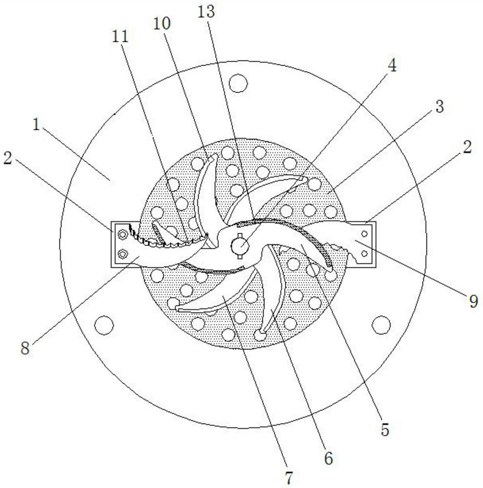
[0030] See figure 1 , The present invention provides a technical solution: a pulping pump pulping component, including:

[0031] The cavity shell 1 has a concave flat columnar pelvis, an annular step is provided at the middle height of the inner wall of the pelvis, and two opposite grooves 2 with different depths are provided at the edge of the upper mouth of the pelvis;

[0032] The sieve plate 3 is a circular plate inlaid on the annular st...


PUM


Abstract

The invention discloses a pulping assembly of a pulping pump. The pulping assembly is composed of a cavity shell, a power extension shaft, a pulping sieve plate, three S-shaped blades and two arc-shaped tool sets, the cavity shell is provided with a basin cavity, the pulping sieve plate is transversely embedded in the basin cavity, and the power extension shaft is installed on the central axis ofthe basin cavity and penetrates through a shaft hole in the pulping sieve plate; the three S-shaped blades are all installed on the power extension shaft, one S-shaped blade is attached to the pulpingsieve plate on the lower portion, and the other two S-shaped blades are installed on the upper portion in a stacked mode; and the two arc-shaped tool sets are oppositely installed on the two sides ofthe basin cavity and face the center of the basin cavity, one arc-shaped tool set is attached to the top face of the uppermost S-shaped blade, and the other arc-shaped tool set is attached to the bottom surface of the S-shaped blade in the middle. The pulping assembly provides a 3G pulping mode of three solid cutting and three dynamic cutting, achieves step-by-step crushing of materials from coarse crushing to fine crushing and then to refined crushing, and enables the pulping pump to have extremely high crushing efficiency and an extremely good crushing effect.

Description

Technical field [0001] The invention relates to the technical field of pulp pumps, in particular to a pulping component of a pulp pump. Background technique [0002] Existing cutting pumps and reamer pumps are simply cut by using a knife formed by the variation of the impeller body. The particles that are broken are lumpy, which can only solve the problem of not blocking the pump, and blockage of pipes and valves will occur, due to the hardness and sharpness of the blade itself. The toughness is limited, the pump throat will be blocked if it breaks and fails after wear, the pump has a short service life and frequent maintenance. Summary of the invention [0003] The purpose of the present invention is to provide a pulping pump pulping assembly to solve the above-mentioned background art problems. [0004] In order to achieve the above objective, the present invention provides the following technical solutions: a pulping pump pulping assembly, including: [0005] The cavity shell has...

Claims


Application Information

Patent Timeline
Patent Type & Authority Applications(China)
IPC IPC(8): F04D7/04F04D29/00F04D29/08F04D29/42B02C18/14B02C18/18B02C23/16
CPCB02C18/14B02C18/18B02C23/16F04D7/045F04D29/00F04D29/007F04D29/086F04D29/42
Inventor 陈斌
Owner 赤壁圆源环保设备科技有限公司
Why Eureka
Try Eureka