
Locking structure

A technology of locking structure and stop plate, applied in the direction of functional valve type, control valve, safety valve, etc., can solve problems such as automatic failure of fireproof check valve, and achieve the effect of reliable operation

Pending Publication Date: 2020-09-01
梅慧
View PDF1 Cites 0 Cited by
  • Summary
  • Abstract
  • Description
  • Claims
  • Application Information

AI Technical Summary

Problems solved by technology

This makes the fire check valve automatically fail in low temperature environment

Method used


Image

  • Locking structure
  • Locking structure
  • Locking structure

Examples


Embodiment 1

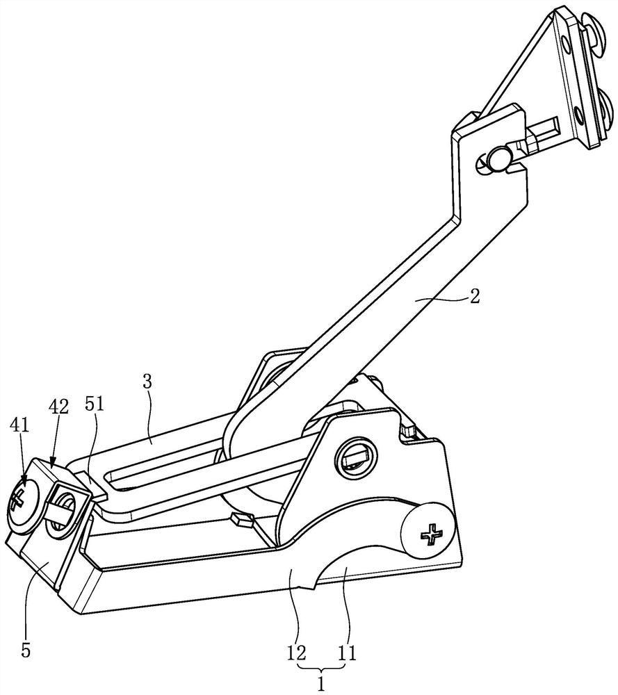
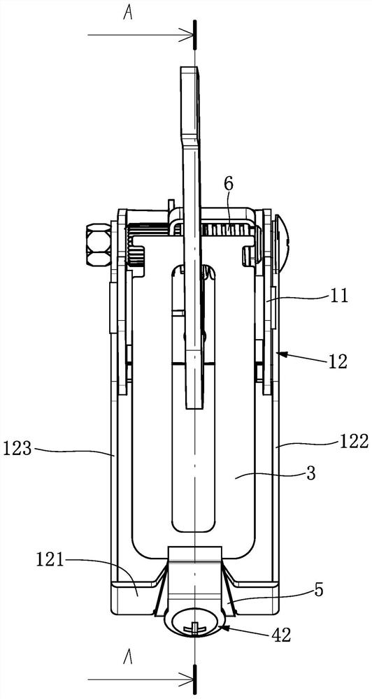
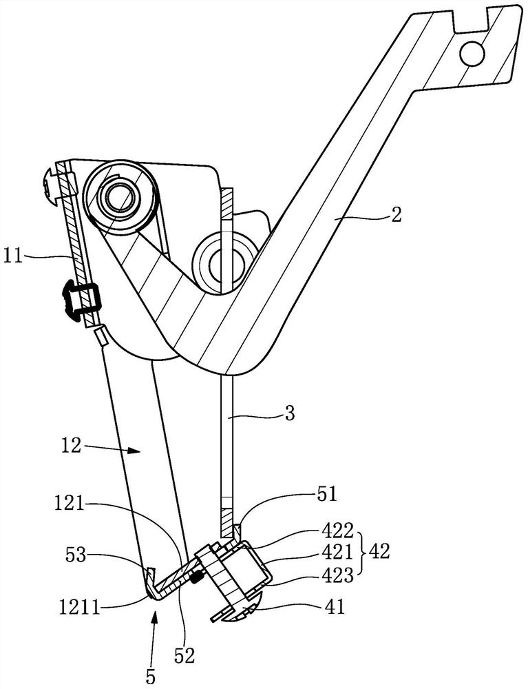
[0028] see figure 1 , the locking structure includes a base 1, a connecting rod 2, an elastic element and a dial 3, the connecting rod 2 and the dial 3 are rotatably arranged on the base 1, one end of the elastic element is arranged on the base 1, and the other end of the elastic element is One end is arranged on the paddle 3 and is used to drive the paddle 3 to rotate relative to the base 1 .

[0029]It should be noted that: the existing elastic element is a torsion spring, and the torsion spring is sleeved on the rotating shaft of the plectrum 3. When the torsion spring is sleeved on the rotating shaft of the plectrum 3, one end of the torsion spring is fixed on the On the base 1 , the other end of the torsion spring abuts against the upper surface of the plectrum 3 . Since the elastic element is not the focus of the present invention, this embodiment does not specifically limit the structure of the elastic element and the connection structure between the elastic element an...

Embodiment 2

[0043] The difference from the first embodiment is that the structure of the fuse assembly is improved in this embodiment.

[0044] see Figure 4 , in this embodiment, the fuse assembly includes at least one fuse piece 42 and at least one fuse ring 43, and the fuse piece 42 includes a first fuse part 422, a second fuse part 423 and is used to control the stop plate 5 on the fastening mechanism 41 The third fuse part 421 in the axial movement range, the first fuse part 422 and the second fuse part 423 are respectively arranged on the fastening mechanism 41, and the third fuse part 421 is used to connect the first fuse part 422 and the second fuse part 423 , the fuse ring 43 is clamped between the first fuse part 422 and the second fuse part 423 .

Embodiment 3

[0046] The difference from the first embodiment is that the structure of the fuse assembly is improved in this embodiment.

[0047] see Figure 5 , in this embodiment, the fuse assembly includes at least one fuse ring 43, the fuse ring 43 is provided with a mounting hole, the fuse ring 43 is sleeved on the fastening mechanism 41 and used to control the axial movement of the stop plate 5 range of motion.


PUM


Abstract

The invention relates to a locking structure, and solves the problem that a fire-proof check valve automatically loses efficacy under a low-temperature environment. The locking structure comprises a foundation bed, a connecting rod, an elastic element and a stirring sheet, wherein one end of the elastic element is arranged on the foundation bed; and the other end of the elastic element is arrangedon the stirring sheet and is used for driving the stirring sheet to rotate relative to the foundation bed. The locking structure also comprises a fusing component, a fastening mechanism and a stop plate, wherein the fastening mechanism is arranged on the foundation bed; the stop plate is arranged on the fastening mechanism and is provided with a locking position and an unlocking position; when the fusing component works, the stop plate is fixed on the locking position through the fusing component, and the stop plate prevents the stirring sheet from rotating relative to the foundation bed; andwhen the fusing component does not work and the fusing component is separated from the stop plate, the elastic element pushes the stop plate to the unlocking position through the stirring sheet.

Description

technical field [0001] The invention relates to a locking structure. Background technique [0002] The locking structure (refer to the utility model patent with the notification number CN206830892 for the specific structure) includes a valve seat, a paddle, a temperature-sensing element and an elastic element. The paddle is rotatably connected to the valve seat. The other end is connected with the paddle and drives the paddle against the temperature sensing element. [0003] Since the temperature sensing element includes the first copper sheet and the second copper sheet, the first copper sheet and the second copper sheet are connected as a whole by fusible solder, the first copper sheet is fixedly connected with the valve seat, the second copper sheet is connected with the plectrum Therefore, when the other end of the elastic element is connected to the plectrum and drives the plectrum to abut against the temperature sensing element, the second copper piece is always subje...

Claims


Application Information

Patent Timeline
IPC IPC(8): F16K15/18F16K17/38
CPCF16K17/383F16K17/386F16K15/1821
Inventor 梅慧
Owner 梅慧
Learn More