
Three-low four-high multi-port base station antenna

A base station antenna, multi-port technology, applied in antennas, antenna coupling, antenna components, etc., can solve problems such as wide horizontal beam width, limited antenna index improvement, cross-area interference, etc., to reduce beam width and optimize the pattern. Indicators, the effect of improving the front-to-back ratio

Active Publication Date: 2020-09-01
江苏泰科微通讯科技有限公司
View PDF13 Cites 3 Cited by
  • Summary
  • Abstract
  • Description
  • Claims
  • Application Information

AI Technical Summary

Problems solved by technology

[0003] In the prior art, the low-frequency multi-port antenna design generally adopts two or more low-frequency linear arrays arranged side by side, and the miniaturization is realized by reducing the distance between the two linear arrays, and at the same time, some special boundaries or elements are added. Devices are used to reduce the mutual coupling between multi-array elements brought about by this common miniaturized design, but this design has limited improvement in antenna indicators, especially in terms of horizontal beam width and front-to-back ratio indicators. If the horizontal distance is too close, the mutual coupling will increase, and the horizontal beam width will be wider in the lower frequency band, which will easily cause cross-regional interference

Method used


Image

  • Three-low four-high multi-port base station antenna
  • Three-low four-high multi-port base station antenna
  • Three-low four-high multi-port base station antenna

Examples


Embodiment Construction

[0041] The present invention is described in further detail now in conjunction with embodiment.

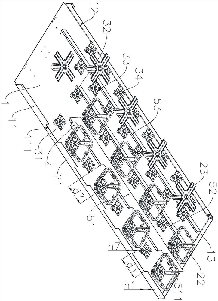
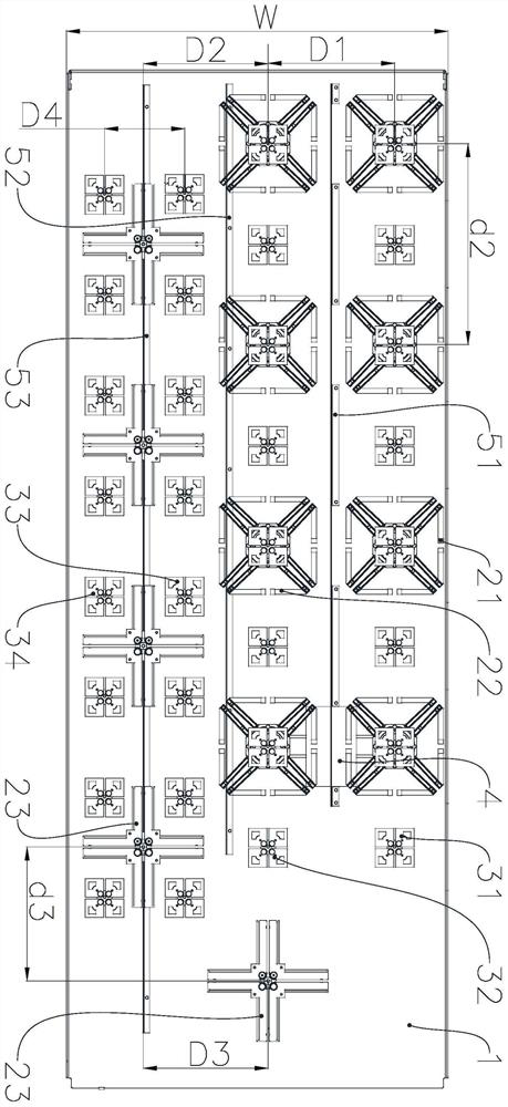
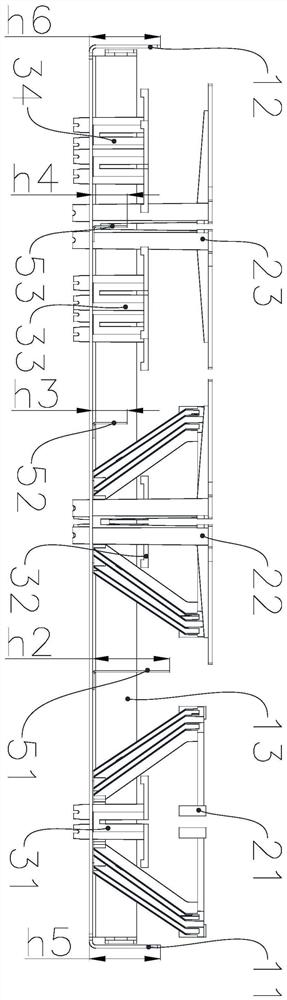
[0042]A three-low four-high multi-port base station antenna, such as Figure 1-2 As shown, including the base plate 1, the two long sides of the base plate 1 are respectively provided with a reflection plate 11 and a reflection plate 2 12, a short side of the base plate 1 is provided with a reflection plate 3 13, and the base plate 1 is provided with parallel or Three sets of overlapping low-frequency radiation arrays and four sets of high-frequency radiation arrays, the low-frequency radiation arrays include low-frequency radiation array 1, low-frequency radiation array 2, and low-frequency radiation array 3, and the high-frequency radiation arrays include high-frequency radiation array 1 and high-frequency radiation array 2 , high-frequency radiation array three and high-frequency radiation array four, low-frequency radiation array one, low-frequency radiation array two, high-fr...


PUM


Abstract

The invention belongs to the technical field of base station antennas. The invention especially relates to a three-low four-high multi-port base station antenna. The antenna comprises a bottom plate,and a reflecting plate I and a reflecting plate II are respectively arranged on two long edges of the bottom plate; a reflecting plate III is arranged on one short edge of the bottom plate; three groups of low-frequency radiation arrays and four groups of high-frequency radiation arrays which are parallel or overlapped with one another are arranged on the bottom plate; the low-frequency radiationarray comprises a low-frequency radiation array I, a low-frequency radiation array II and a low-frequency radiation array III; the high-frequency radiation array comprises a high-frequency radiation array I, a high-frequency radiation array II, a high-frequency radiation array III and a high-frequency radiation array IV; the low-frequency radiation arrayI, the low-frequency radiation arrayII, thehigh-frequency radiation arrayI, the high-frequency radiation arrayII, the high-frequency radiation array III and the high-frequency radiation array IV each comprise a plurality of first low-frequencyoscillators, a plurality of second low-frequency oscillators, a plurality of third low-frequency oscillators, a plurality of first high-frequency oscillators, a plurality of second high-frequency oscillators, a plurality of fourth high-frequency oscillators.

Description

technical field [0001] The invention belongs to the technical field of base station antennas, and in particular relates to a three-low and four-high multi-port base station antenna. Background technique [0002] With the rapid development of the mobile communication system, the complexity of the system is getting higher and higher, and the antenna, as an important part of it, is also facing a serious test. In recent years, multiple network standards of 2G, 3G, and 4G have coexisted and co-located, making site resources increasingly tight, especially in cities, where there are no redundant site resources available. Faced with the fact that multi-system antenna co-site can greatly save space on the sky and construction resources, multi-port antennas have become a trend, providing a technical basis for multi-system multi-standard co-site, but the inevitable problem of multi-port antennas is that the antenna size is too large, Brings installation and security risks. Especially...

Claims


Application Information

Patent Timeline
Patent Type & Authority Applications(China)
IPC IPC(8): H01Q19/185H01Q21/30H01Q1/36H01Q1/52
CPCH01Q19/185H01Q21/30H01Q1/36H01Q1/364H01Q1/523
Inventor 丁勇王长江刘义成
Owner 江苏泰科微通讯科技有限公司
Learn More