
Full-bridge IGBT drive circuit and implementation method thereof

A driving circuit and circuit technology, which is applied to electrical components, output power conversion devices, etc., can solve the problems that IGBT driving circuits cannot satisfy mutual exclusion, synchronization and intermittentness at the same time, so as to solve intermittent problems and increase the death rate. Zone delay, the effect of solving synchronization problems

Active Publication Date: 2020-09-01
INTEGRATED ELECTRONICS SYST LAB
View PDF10 Cites 2 Cited by
  • Summary
  • Abstract
  • Description
  • Claims
  • Application Information

AI Technical Summary

Problems solved by technology

[0004] The purpose of the present invention is to provide a full-bridge IGBT drive circuit and its implementation method, which aims to solve the problem that the IGBT drive circuit in the prior art cannot satisfy mutual exclusion, synchronization and intermittent at the same time, and realize low-cost, low-complexity Degree circuit realizes the driving of IGBT

Method used


Image

  • Full-bridge IGBT drive circuit and implementation method thereof
  • Full-bridge IGBT drive circuit and implementation method thereof
  • Full-bridge IGBT drive circuit and implementation method thereof

Examples


Embodiment Construction

[0031] In order to clearly illustrate the technical features of the present solution, the present invention will be described in detail below through specific implementation methods and in conjunction with the accompanying drawings. The following disclosure provides many different embodiments or examples for implementing different structures of the present invention. To simplify the disclosure of the present invention, components and arrangements of specific examples are described below. Furthermore, the present invention may repeat reference numerals and / or letters in different instances. This repetition is for the purpose of simplicity and clarity and does not in itself indicate a relationship between the various embodiments and / or arrangements discussed. It should be noted that components illustrated in the figures are not necessarily drawn to scale. Descriptions of well-known components and processing techniques and processes are omitted herein to avoid unnecessarily lim...


PUM


Abstract

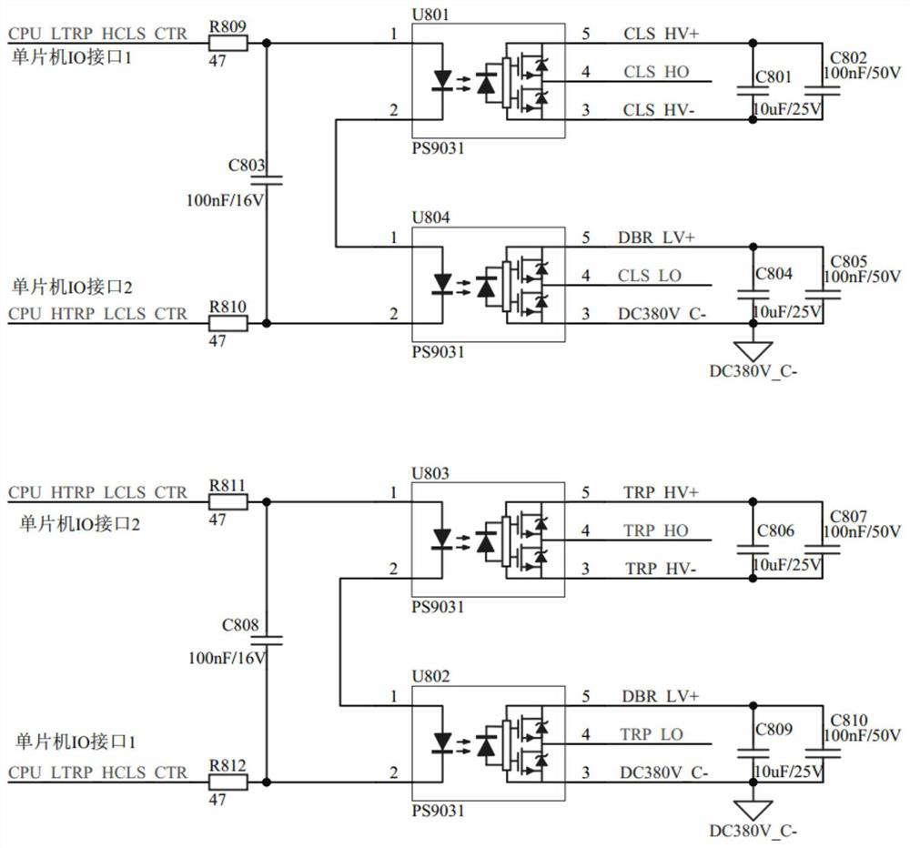
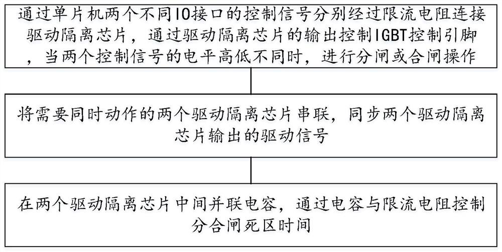
The invention provides a full-bridge IGBT drive circuit and an implementation method thereof. According to the invention, the two IO interfaces of the CPU are used as control signals at the same time;when the two control signal levels are the same; the IGBT driving signals are not output, the full-bridge circuit does not act, the driving signals are output and the full-bridge circuit acts only when one control signal is low and the other control signal is high, and when the levels of the two control signals are different and overturn at the same time, the driving signals are switched and theoutput voltage of the full-bridge circuit overturns, so that the problem of mutual exclusiveness is solved; the driving ends of the driving chips for controlling the opening and closing of the two groups of IGBTs are connected in series, and a current-limiting resistor is connected in series in a loop, so that the two groups of IGBTs for opening and closing operations are ensured to be simultaneously switched on and off, and the problem of synchronism is solved; the input ends of the two driving chips which are connected in series are connected with the small-capacity capacitor in parallel, the capacitor and the current-limiting resistor form an RC time-delay circuit, dead zone time delay of switching-on and switching-off operation is increased, immediate switching-off after switching-on or immediate switching-on after switching-off is prevented, and the intermittent problem is solved.

Description

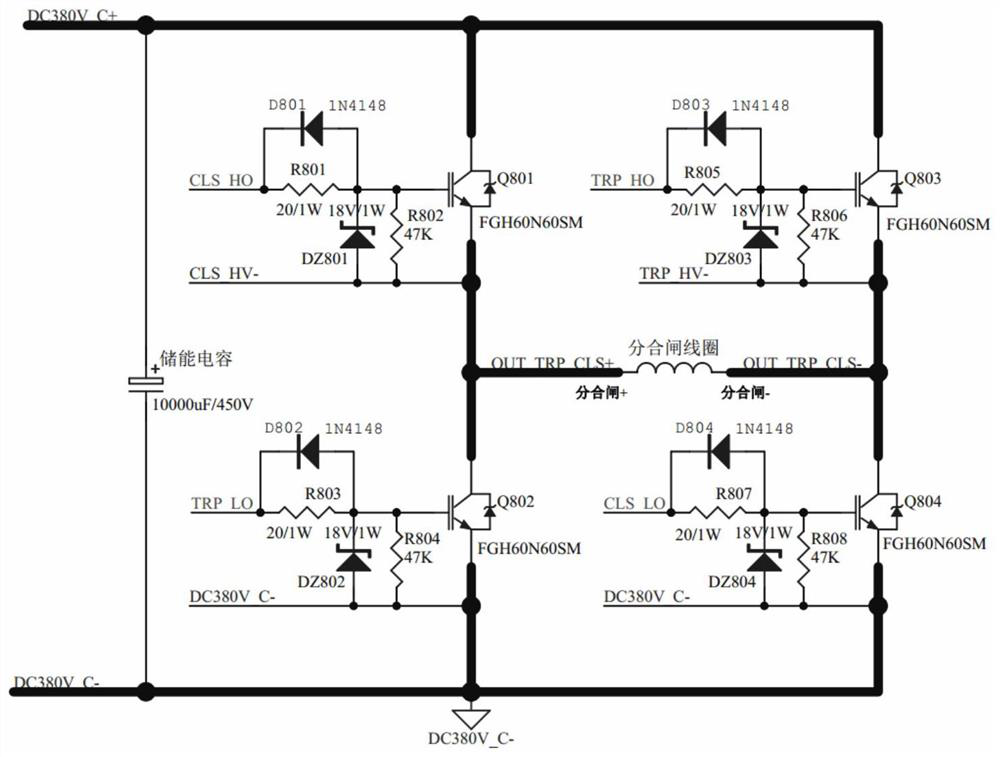
technical field [0001] The invention relates to the technical field of full-bridge IGBT drive, in particular to a full-bridge IGBT drive circuit and its implementation method. Background technique [0002] In the distribution network power supply system, the permanent magnet operating mechanism is widely used in the distribution line because of its advantages of simple structure, high reliability and fast operation speed. The opening and closing operation of the monostable permanent magnet operating mechanism shares an electromagnetic coil. Applying a DC voltage in the forward direction is closing, and applying a DC voltage in the reverse direction is opening. The power output stage of the conventional drive circuit is a full bridge composed of 4 IGBTs. circuit, the bus voltage is DC220V or DC380V, such as figure 1 As shown, Q801 and Q804 are turned on at the same time as closing, and Q803 and Q802 are turned on at the same time as opening. [0003] The four IGBTs in the f...

Claims


Application Information

Patent Timeline
Patent Type & Authority Applications(China)
IPC IPC(8): H02M1/088H02M1/38
CPCH02M1/088H02M1/38H02M1/385
Inventor 崔士军张立伟徐凯刘兰兵
Owner INTEGRATED ELECTRONICS SYST LAB
Learn More