
Substrate for in-situ measurement of stress combined with finite element in laser net shaping

A net-shaping, finite element technology, applied in the field of in-situ monitoring of additive manufacturing, can solve the problems of increasing the time cost, high economic cost, and increased cost of the laser net-shaping process.

Active Publication Date: 2021-04-13
TSINGHUA UNIV +1
View PDF7 Cites 0 Cited by
  • Summary
  • Abstract
  • Description
  • Claims
  • Application Information

AI Technical Summary

Problems solved by technology

The traditional substrate has the disadvantages of high economic cost and high time cost, that is, the existing measurement scheme is to re-polish and smooth the measurement surface of the substrate before realizing the in-situ monitoring of the substrate deformation in the laser net shaping process. degree of processing
Obviously, the polishing treatment and surface flatness treatment of the substrate measurement surface before in-situ monitoring will not only increase the cost, but also increase the time cost of the laser net shaping process due to the treatment process

Method used


Image

  • Substrate for in-situ measurement of stress combined with finite element in laser net shaping
  • Substrate for in-situ measurement of stress combined with finite element in laser net shaping
  • Substrate for in-situ measurement of stress combined with finite element in laser net shaping

Examples


Embodiment Construction

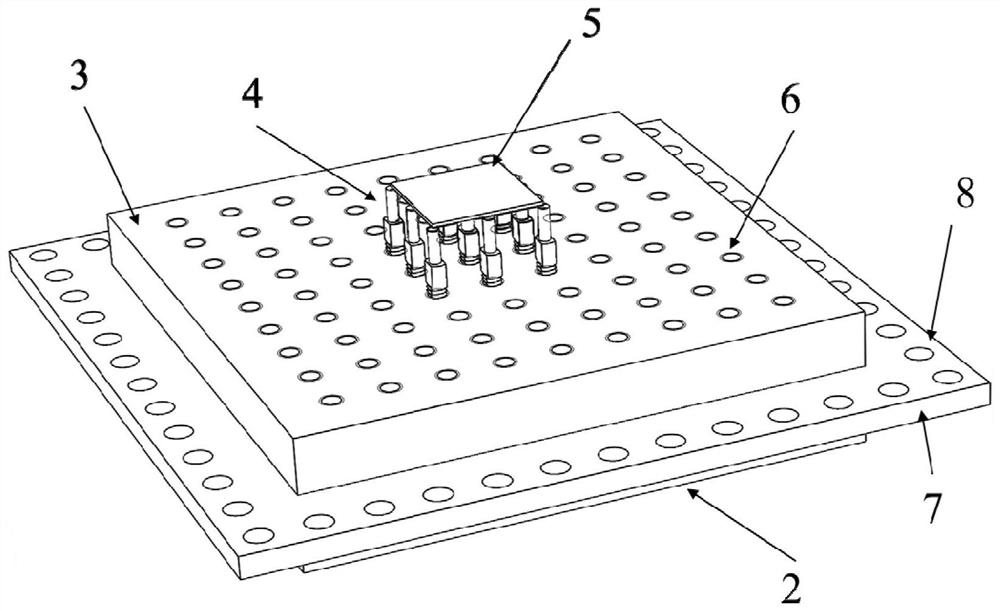
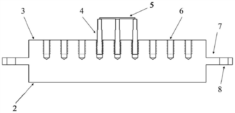
[0015] The substrate proposed by the present invention for in-situ measurement of stress in combination with finite elements in laser net shaping has a structure such as figure 1 As shown, it includes a substrate body 1, a specular reflection sheet 5 and a reflection sheet positioning bolt 4; substrate fixing wings 7 are processed around the substrate body 1, and substrate positioning holes 8 are opened on the substrate fixing wings 7; the substrate body 1 The upper surface is the manufacturing surface 2, the lower surface of the substrate body 1 is the measuring surface 3, and the measuring surface 3 is processed with evenly distributed measuring surface thread lattice holes 6, and the reflector positioning bolts 4 are connected with the measuring surface thread lattice holes 6 Cooperating with each other, the specular reflection sheet 5 is fixed on the end of the positioning bolt 4 of the reflection sheet.

[0016] Below in conjunction with accompanying drawing, introduce c...


PUM

PropertyMeasurementUnit
thicknessaaaaaaaaaa
elastic modulusaaaaaaaaaa

Abstract

The invention relates to a substrate used for in-situ measurement of stress in combination with finite elements in laser net shaping, and belongs to the technical field of in-situ monitoring in additive manufacturing. The base plate includes a base plate body, a mirror reflection sheet and a positioning bolt of the reflection sheet; base plate fixing wings are processed around the base body body, the upper surface of the base body body is a manufacturing surface, the lower surface is a measurement surface, and threaded dot matrix holes are processed on the measurement surface. The positioning bolts of the reflection sheet cooperate with the threaded lattice holes of the measurement surface, and the specular reflection sheet is fixed at the end of the positioning bolts of the reflection sheet. In the substrate of the present invention, a specular reflection sheet is used to replace the polishing process of the measurement surface of the substrate in the prior art, and the deformation monitoring area of ​​the substrate can be adjusted according to measurement requirements. After the parts manufactured on the substrate are cut off from the substrate and before in-situ monitoring, the requirements of the coherent gradient measurement system can be met by simply replacing the specular reflector, which saves economic and time costs.

Description

technical field [0001] The invention relates to a substrate used for in-situ measurement of stress in combination with finite elements in laser net shaping, and belongs to the technical field of in-situ monitoring for additive manufacturing. Background technique [0002] Additive Manufacturing (AM for short), also known as 3D printing, is a manufacturing method that combines computer 3D model data and consolidates them into a whole by point-by-point accumulation. Compared with traditional manufacturing methods, additive manufacturing has many advantages, such as direct manufacturing of composite materials / structural products without design constraints. Especially the laser engineered net shaping process (Laser Engineered Net Shaping, referred to as LENS), has great development potential in the field of aerospace. Although additive manufacturing is developing rapidly, due to the particularity of the manufacturing method, there are still many problems in the products of addit...

Claims


Application Information

Patent Timeline
Patent Type & Authority Patents(China)
IPC IPC(8): B29C64/386B33Y50/00
CPCB33Y50/00B29C64/386
Inventor 谢惠民李加强石文雄刘胜
Owner TSINGHUA UNIV
Learn More